Ultra wide band radar localization

a wide band radar and ultra-wide band technology, applied in the field of localization, can solve the problems of interfering with or preventing such sensing capabilities, and achieve the effects of improving positioning, high flexibility of overall solution, and keeping track of motion

Inactive Publication Date: 2018-02-08
HUMATICS CORP
View PDF3 Cites 22 Cited by
  • Summary
  • Abstract
  • Description
  • Claims
  • Application Information

AI Technical Summary

Benefits of technology

[0010]By correlating real-time data and extracting edges or features from the data with the features from aerial imagery it is possible to provide a position correction that can be used not only for autonomous driving, but for improving vehicle-related applications that require accurate positioning. The dual aspect of reactive contour following coupled with next-generation localization provides a highly flexible overall solution.
[0011]The present invention also allows for tremendous variation in terms of the infrastructure used to support this UWB-based system. Active UWB “beacons” as well as passive reflectors can be affixed in an infin

Problems solved by technology

These conditions would otherwise interfere with or preclude such sensing capabilities in other non-wideband

Method used


Image

  • Ultra wide band radar localization
  • Ultra wide band radar localization
  • Ultra wide band radar localization

Examples


Embodiment Construction

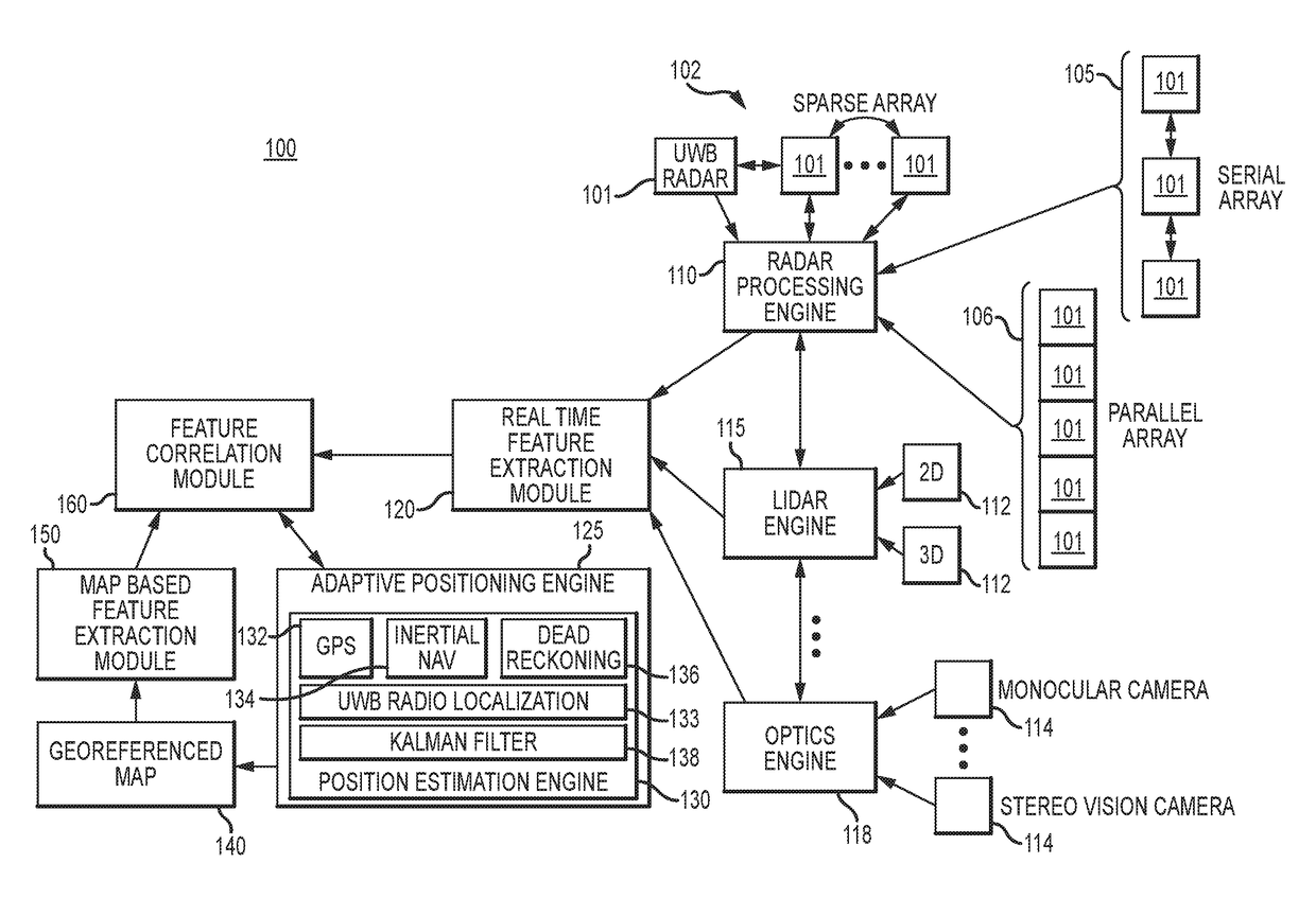
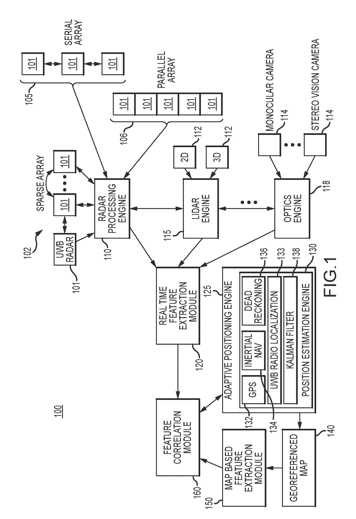
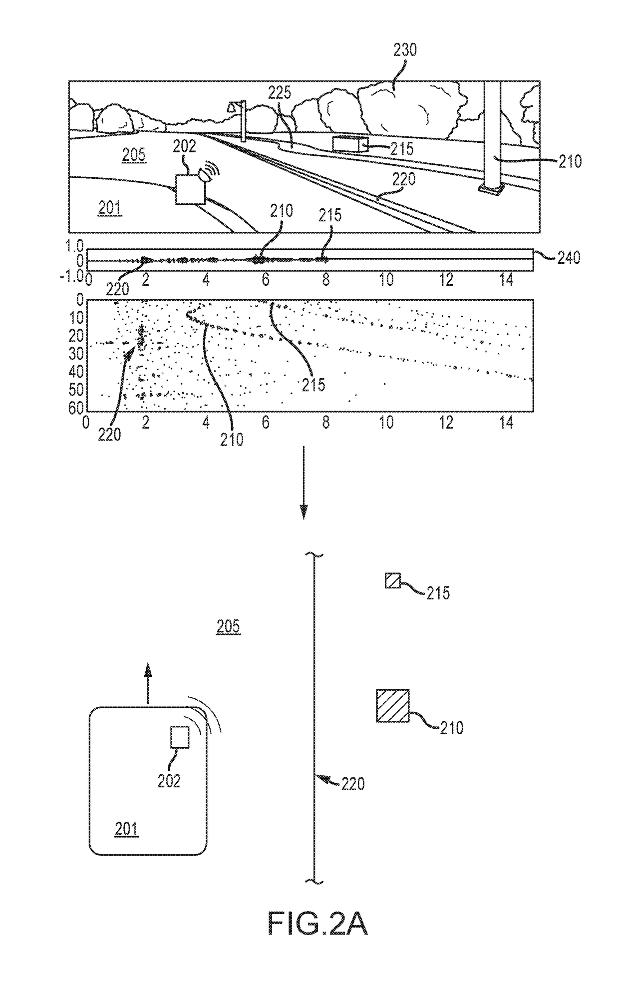
[0023]UWB Radar Localization correlates coherent radar returns with features extracted from a georeferenced map to refine positional information of an object. Data collected from one or more UWB Radars along with other real-time sensors can be processed to identify discrete real-time features or characteristic returns such as a pole or building. These real-time extracted features can be correlated with features extracted from a georeferenced map to provide a position correction. As the UWB Radar(s) location and orientation with respect to the object is (are) known the precise location and pose of the object on the georeferenced map can be determined by matching features found in the map or imagery with those of the coherent return.

[0024]An object may be associated with a plurality of UWB Radars affixed at various positions and orientations. Each of the UWB Radars are, according to one embodiment of the present invention, coupled to a Radar Processor or Radar Orchestration engine tha...


PUM


Abstract

Coherent radar returns gained from Ultra-Wideband Radars are correlated with features extracted from a georeferenced map to refine positional information and pose of an object. Data collected from one or more UWB Radars and other real time sensors affixed on an object can be processed to identify discrete edges or characteristic returns such as a pole, building or the like. These coherent returns can be correlated with features extracted from a georeferenced map. As the UWB Radar(s) location and orientation with respect to the object is (are) known the precise location and pose of the object on the georeferenced map can be determined by matching features found in the map or imagery with those of the coherent return. Moreover the configuration of the UWB Radars can be modified based on a perception of the local environment.

Description

RELATED APPLICATION[0001]The present application relates to and claims the benefit of priority to U.S. Provisional Patent Application No. 62 / 293079 filed Feb. 9, 2016 and U.S. Provisional Patent Application No. 62 / 364004 filed Jul. 19, 2016, both of which are hereby incorporated by reference in their entirety for all purposes as if fully set forth herein.BACKGROUND OF THE INVENTION[0002]Field of the Invention[0003]Embodiments of the present invention relate, in general, to localization and more particularly to spatial localization (or positioning) of objects using Ultra-Wide Band (“UWB”) RADAR.[0004]Relevant Background[0005]Radar is used in many applications to detect target objects such as airplanes, military targets, and vehicles. A radar system may detect the range (i.e., distance) to a target object by determining the roundtrip delay period between the transmission of a radar signal and the receipt of the signal returning to the radar after it bounces off the target object. This...

Claims


Application Information

Patent Timeline
IPC IPC(8): G01C21/00G01S13/86G01S13/02
CPCG01C21/005G01S13/0209G01S13/865G01S13/931G01S13/74G01S13/86G01S13/876G01S7/2955G01S13/874G01S2013/9329G01S2013/93274G01S2013/93271
Inventor BRUEMMER, DAVIDDEWBERRY, BRANDON
Owner HUMATICS CORP
Why Eureka
Try Eureka