Surgical microscope with gesture control and method for a gesture control of a surgical microscope

a surgical microscope and gesture control technology, applied in the field of surgical microscopes, can solve problems such as loss of focus, delay in patient operation, and disturbed surgical workflow

Active Publication Date: 2018-02-22
LEICA INSTR SINGAPORE PTE
View PDF3 Cites 5 Cited by
  • Summary
  • Abstract
  • Description
  • Claims
  • Application Information

AI Technical Summary

Benefits of technology

[0017]Further advantages of the inventive surgical microscope with gesture control is an intuitive operation of the surgical microscope, the possibility of an interactive operation of the surgical microscope which is similar to operating systems of mobile phones and the possibility to implement the inventive gesture control with components already present in the surgical microscope, i.e. a 3-D camera or a differential interference contrast unit (DIC-unit), which renders the upgrade of existing surgical microscopes as inexpensive. Furthermore, the present invention does not alter the appearance of existing surgical microscopes as it does not add any visible components such as buttons, foot switches or mouth switches to the surgical microscope.
[0018]A gesture is to be understood as a movement of an object such as a finger or a tool, as a relative movement of two objects to each other, or as a rotation of one or more objects. The rotation of one or more objects may be performed around any of the spatial axes, e.g. perpendicular or parallel to the imaging axis. Rotations around the spatial axes may be arbitrarily combined.
[0019]The inventive surgical microscope may comprise a set of complicated gestures detectable by the detection unit, for instance gestures like thumbs up, open palm or closed palm. Furthermore, detec

Problems solved by technology

However, the surgical workflow is disturbed when the surgeon changes microscope parameters such as exemplarily focus, zoom and field of view, i.e. the operation or inspection area currently viewed.
With such adjustment operations of the surgeon, the surgical workflow is interrupted and can lead to a loss of focus for the surgeon, which inconveniences the surgeon as he or she must look up from the microscope eyepiece and adapt to different ambient light conditions.
Furthermore, such adjustments may delay the operation on a patient.
Additionally, due to the need to put down the surgica

Method used


Image

  • Surgical microscope with gesture control and method for a gesture control of a surgical microscope
  • Surgical microscope with gesture control and method for a gesture control of a surgical microscope
  • Surgical microscope with gesture control and method for a gesture control of a surgical microscope

Examples


first embodiment

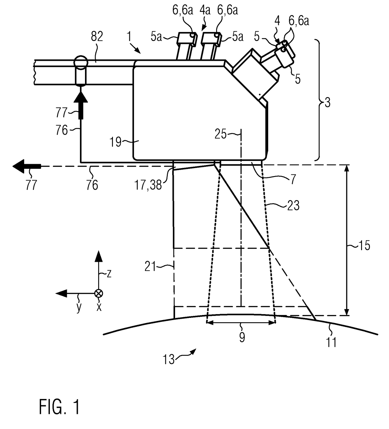
[0098]FIG. 1 shows a schematic side view of an inventive surgical microscope 1, which surgical microscope 1 comprises an optical imaging system 3, which optical imaging system 3 comprises, for instance, a stereoscopic eyepiece 4 comprising eyepieces 5, a stereoscopic assistant's eyepiece 4a comprising assistant's eyepieces 5a located at the side of the surgical microscope 1 and an objective 7. The optical imaging system 3 determines a field of view 9 which is a portion of the inspection area 11 which may be a patient 13.

[0099]The field of view 9 is determined by the numerical aperture of the optical imaging system 3 and a working distance 15, which working distance 15 is measured along a z-axis. The field of view 9 extends along the x-axis and y-axis.

[0100]The surgical microscope 1 further comprises a gesture detection unit 17 which is attached to the housing 19 of the surgical microscope 1. The gesture detection unit 17 acts as a reference point 38 in the embodiments shown in FIG. ...

second embodiment

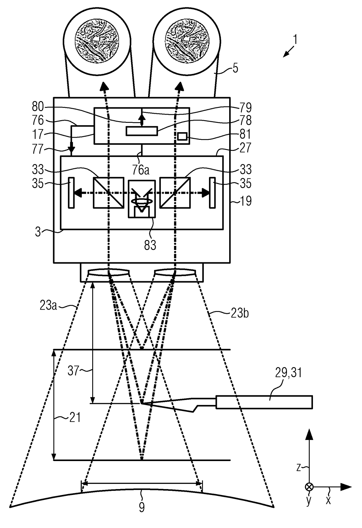
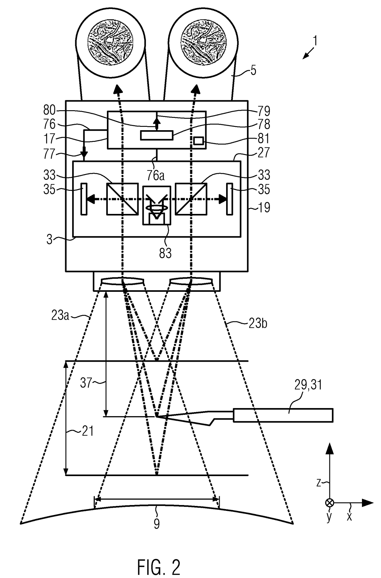
[0107]FIG. 2 shows a schematic front view of the inventive surgical microscope 1 in which the gesture detection unit 17 is embodied integrally in the housing 19 of the surgical microscope 1. This embodiment does not comprise the stereoscopic assistant's eyepiece 4a.

[0108]In the embodiment shown in FIG. 2, the 3D-camera 27 of the surgical microscope 1 provides the distance information of objects 29 via a signal line 76.

[0109]The gesture detection unit 17 further comprises a movement detection module 78, which is provided by the signal line 76a with data from the 3D-camera 27.

[0110]The movement detection unit 78 provides a movement-data signal 80 via a movement-data line 79 to the gesture detection unit 17.

[0111]Via the signal line 76, the gesture detection unit 17 outputs a control signal 77 to the optical imaging system 3. The control signal 77 and the movement-data signal 80 are indicated by arrows.

[0112]The gesture detection unit 17 further comprises a relationship mapping unit 8...


PUM


Abstract

The present invention relates to a surgical microscope (1) with a field of view (9) and comprising an optical imaging system (3) which images an inspection area (11) which is at least partially located in the field of view (9), and to a method for a gesture control of a surgical microscope (1) having an optical imaging system (3). Surgical microscopes (1) of the art have the disadvantage that an adjustment of the microscope parameters, for instance the working distance, field of view (9) or illumination mode, requires the surgeon to put down his or her surgical tools, look up from the microscope's eyepiece (5) and perform the adjustment by operating the microscope handles. Also foot switches and mouth switches where proposed, whereas those are not intuitively operated, require training and are less accurate than hand control of the microscope handles. Thus, the surgeon may lose his or her focus, is confronted with inconveniences and delays and bears an increased risk of contamination. In order to overcome the above disadvantages, the present invention provides a surgical microscope (1) which is characterized in that the surgical microscope (1) further comprises a gesture detection unit (17) for detection of a movement (65) of an object (29) such as at least one of a finger and a tool, and in that the gesture detection unit (17) is connected to the optical imaging system (3) via a signal line (76) and in that the gesture detection unit (17) is configured to output a control signal (77) via the signal line (76) to the optical imaging system (3) depending on the movement (65) of the object (29), the optical imaging system (3) being configured to alter its state depending on the control signal (77). The invention further provides a method for gesture control of the inventive surgical microscope (1).

Description

CROSS REFERENCE TO RELATED APPLICATIONS[0001]This application claims priority of European patent application number 16184312.3 filed Aug. 16, 2016, the entire disclosure of which is incorporated by reference herein.FIELD OF THE INVENTION[0002]The invention relates to a surgical microscope with a field of view and comprising an optical imaging system which images an inspection area which is at least partially located in the field of view. The invention further relates to a method for a gesture control of a surgical microscope having an optical imaging system.BACKGROUND OF THE INVENTION[0003]Surgical microscopes are optical devices intended to provide low magnification at the operation area and a relatively large working distance so that the operation area is easily accessible for the surgeon to perform surgical operations. The operation area or inspection area is commonly imaged by an optical imaging system which provides an image of the inspection area either to the eyes of the surg...

Claims


Application Information

Patent Timeline
IPC IPC(8): A61B34/00G06F3/0484G02B21/00
CPCA61B34/25G06F3/04847A61B90/20G06F3/0304G02B21/368G02B21/0012G02B21/32G06F3/011G06F3/017G02B21/22G02B21/364A61B2017/00207
Inventor THEMELIS, GEORGE
Owner LEICA INSTR SINGAPORE PTE
Why Eureka
Try Eureka