Watch Winder and Method of Winding a Watch

a technology of watch winder and watch, which is applied in the direction of clock apparatus, instruments, horology, etc., can solve the problems of excessive wear and tear of precise gear trains of expensive watches, excessive wear and tear of unnecessary winding, etc., and achieve the effect of eliminating operational nois

Inactive Publication Date: 2018-02-22
BOROZDIN VASILIY +1
View PDF2 Cites 6 Cited by
  • Summary
  • Abstract
  • Description
  • Claims
  • Application Information

AI Technical Summary

Benefits of technology

[0010]The objective of present invention is a winding apparatus and method for automatic mechanical watches. The apparatus and method of this invention overcome some deficiencies of the prior art. The apparatus and method of this invention can detect watch main spring state during winding process, detect under winded and fully winded state of the spring, automatically find direction of rotation for winding, completely eliminates operational noise.

Problems solved by technology

No feedback on the actual winding state of the watch main spring is utilized for prior art watch winders, resulting in under winding, or excessive wear and tear due to unnecessary winding when main spring is already fully winded.
The first results in stopped watch, whereas the latter causes mechanical tear of precise gear train of expensive watch, specifically slipping clutch of the watch.
With winding still in-progress for already winded main spring, the excessive mechanical energy dissipates in the form of small pulses generated by mechanical watch gear train, specifically by slipping mechanism.
Nevertheless, the previous art does not allow determination of the winded state of the watch main spring, and no sensing means claimed.
As a result, operation of the prior art watch winder within optimal partially winded automatic watch main spring state involves significant effort input by the user, and does not guarantee accuracy.
Another shortcoming of the previous art is mechanical noise caused by friction, gears, and motor.

Method used


Image

  • Watch Winder and Method of Winding a Watch
  • Watch Winder and Method of Winding a Watch
  • Watch Winder and Method of Winding a Watch

Examples


Embodiment Construction

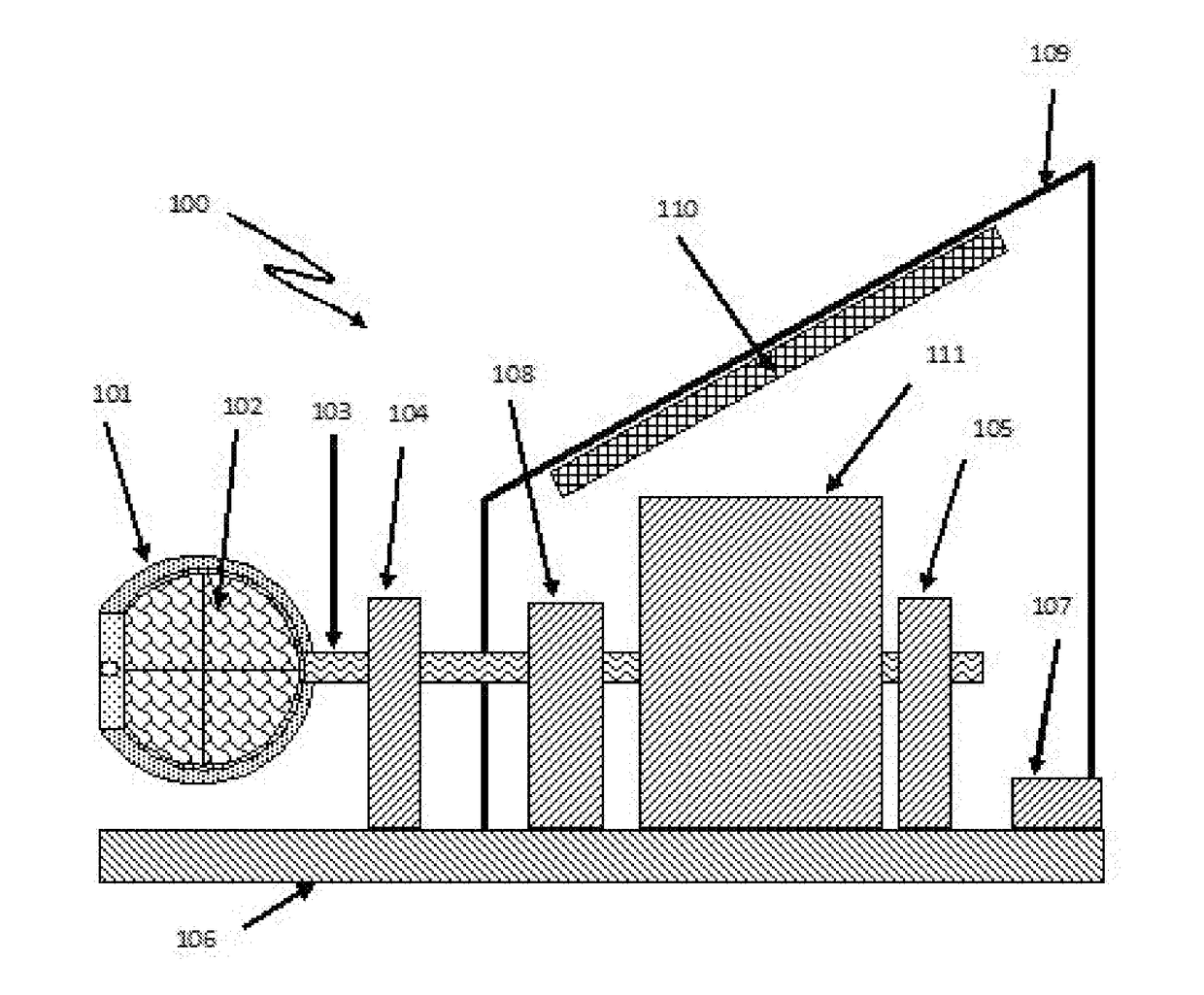
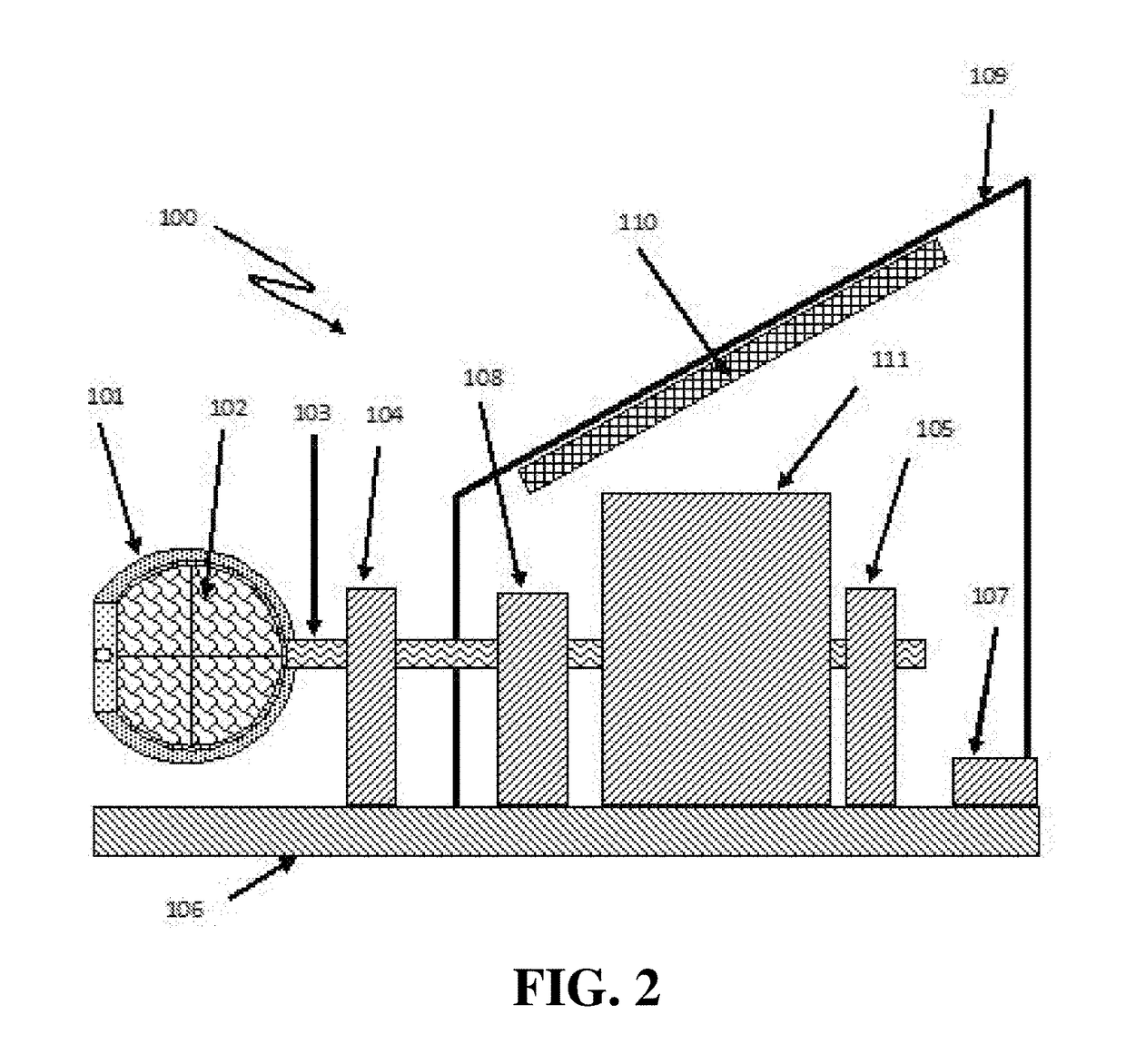
[0022]Automatic watch main spring winding mechanism is known to involve numerous designs for transfer swinging rotation of the winding weight (rotor) into main spring tension, thus allowing mechanical energy accumulation within the main spring for watch movement. With fully winded main spring and continuing winding, that energy is partially released thanks to known safety mechanisms such as, for example, slipping clutch. Once the main spring is fully winded, the safety mechanism goes into action, causing mechanical feedback not present during normal winding process. As a result, the watch mechanism receives a series of small mechanical pulses. The present embodiment apparatus allows sensing of those small pulses, whereas method implemented with microcomputer software, allows determination of the main spring winding state.

[0023]The above mentioned small pulses result in small variations in rotational speed of the watch winder shaft, whereas average rotation speed of the shaft with at...


PUM


Abstract

A watch winder fully winds the watch main spring of various brands of automatic watches, avoiding wear and tear caused by excessive winding caused by prior art winders. In contrast with prior art watch winders, which wind watch main springs a predetermined number of turns, the inventive watch winder precisely detects a fully winded condition of the watch main spring, and stops winding. Prior art watch winders lack that sensing feature, so they continue winding fully winded watches until the predetermined number of turns has been completed. Additionally, the inventive watch winder eliminates the need to guess the number of turns and direction of rotation for different watches. The inventive subject matter further includes methods, which employ deviations in rotation speed to determine watch main spring winding states, such as under-winded, mid-winded, and fully-winded.

Description

[0001]This application claims the benefit of priority to U.S. Provisional Application No. 62 / 373,865 filed Aug. 11, 2016. All extrinsic materials identified herein are incorporated by reference in their entirety.FIELD OF THE INVENTION[0002]The field of the invention is winding apparatuses and method for keeping self-winding automatic mechanical watches winded during periods of no use.BACKGROUND[0003]The following background discussion includes information that may be useful in understanding the present invention. It is not an admission that any of the information provided herein is prior art or relevant to the presently claimed invention, or that any publication specifically or implicitly referenced is prior art.[0004]Automatic mechanical watches employ spring mechanism for storing energy for watch movement. When not in use, winding of the spring is commonly performed by automatic watch winders. Usually, those machines periodically wind automatic watches for pre-determined number of...

Claims


Application Information

Patent Timeline
Patent Type & Authority Applications(United States)
IPC IPC(8): G04C1/04
CPCG04C1/04G04D7/009G04C1/06
Inventor LIEB, YULIYBOROZDIN, VASILIY
Owner BOROZDIN VASILIY
Why Eureka
Try Eureka