CPU Security Mechanisms Employing Thread-Specific Protection Domains

a security mechanism and protection domain technology, applied in the field of computer processing systems, can solve the problems of high resource consumption, power-hungry hardware, and a process switch, and achieve the effects of reducing the number of resources

Active Publication Date: 2018-03-01
MILL COMPUTING
View PDF3 Cites 26 Cited by
  • Summary
  • Abstract
  • Description
  • Claims
  • Application Information

AI Technical Summary

Benefits of technology

[0025]The hardware registers that store the descriptors for the predefined memory regions of the address space can be accessed and processed in order to perform protection checking before querying the at least one hardware table that stores the descriptors for protection checking. In certain circumstances, the protection checking carried out by accessing and processing the hardware registers that store the descriptors for the predefined memory regions of the address space avoids the protection checking carried out by accessing and processing the at least one hardware table that stores the descriptors.

Problems solved by technology

However, the total space used by even thousands of very large programs will not approach the size representable in 64 bits, so aliasing need not occur and address extension is unnecessary in 64-bit machines.
Because all this must be performed for every reference to memory, and specifically must be performed before cache can be accessed, the necessary hardware is power hungry, large and on the critical path for program performance.
Changing from running one process to running another is called a process switch and is very expensive in machine terms because of the amount of state that has to be saved and restored as the process context is changed.
Communication between processes (also known as inter-process communication) can be quite difficult and resource-intensive.
Such protocols are difficult to write and a frequent source of subtle bugs.

Method used


Image

  • CPU Security Mechanisms Employing Thread-Specific Protection Domains
  • CPU Security Mechanisms Employing Thread-Specific Protection Domains
  • CPU Security Mechanisms Employing Thread-Specific Protection Domains

Examples


Embodiment Construction

[0054]Illustrative embodiments of the disclosed subject matter of the application are described below. In the interest of clarity, not all features of an actual implementation are described in this specification. It will of course be appreciated that in the development of any such actual embodiment, numerous implementation-specific decisions must be made to achieve the developer's specific goals, such as compliance with system-related and business-related constraints, which will vary from one implementation to another. Moreover, it will be appreciated that such a development effort might be complex and time-consuming but would nevertheless be a routine undertaking for those of ordinary skill in the art having the benefit of this disclosure.

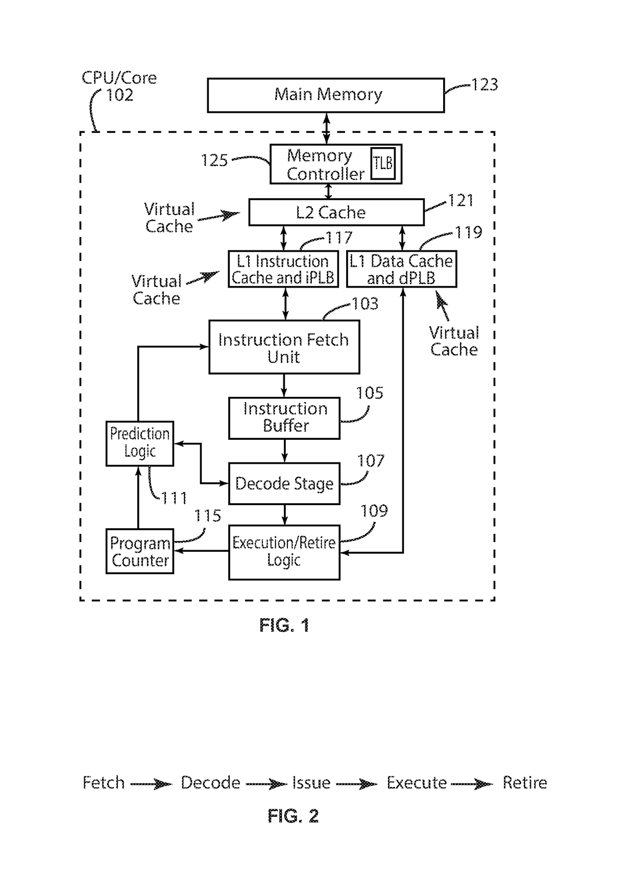
[0055]As used herein, the term “operation” is a unit of execution, such as an individual add, load, store or branch operation.

[0056]The term “instruction” is a unit of logical encoding including zero or more operations. For the case where an instr...


PUM


Abstract

A computer processor includes an instruction processing pipeline that interfaces to a hierarchical memory system employing an address space. The instruction processing pipeline includes execution logic that executes at least one thread in different protection domains over time, wherein the different protection domains are defined by descriptors each including first data specifying a memory region of the address space employed by the hierarchical memory system and second data specifying permissions for accessing the associated memory region. The address space can be a virtual address space or a physical address space. The protection domains can be associated with different turfs each representing a collection of descriptors. A given thread can execute in a particular protection domain(turf), one protection domain (turf) at a time with the particular protection domain (turf) selectively configured to change over time.

Description

BACKGROUND OF THE INVENTION1. Field[0001]The present disclosure relates to computer processing systems.2. State of the Art[0002]A computer processor and the program which it executes needs places to put data for later reference. A computer processor will typically have many such places, each with its own trade off of capacity, speed of access, and cost. Usually these are arranged in a hierarchal manner referred to as the memory system of the computer processing system, with small, fast, costly places used for short lived small data and large, slow and cheap places used for what doesn't fit in the small, fast, costly places. The hierarchical memory system typically includes the following components arranged in order of decreasing speed of access:[0003]a register file or other form of fast operand storage;[0004]one or more levels of cache memory (one or more levels of the cache memory can be integrated with the processor (on-chip cache) or separate from the processor (off-chip cache);...

Claims


Application Information

Patent Timeline
Patent Type & Authority Applications(United States)
IPC IPC(8): G06F12/0893G06F9/00G06F12/0875
CPCG06F9/00G06F12/0875G06F2212/60G06F12/0893G06F12/1441G06F9/3004G06F9/3009G06F9/3802G06F9/3851G06F9/468
Inventor GODARD, ROGER RAWSONKAHLICH, ARTHUR DAVIDSCHUKAT, JANEDWARDS, WILLIAM
Owner MILL COMPUTING
Why Eureka
Try Eureka