Surge protection device

a protection device and surge protection technology, applied in the direction of spark gap details, emergency protection circuit arrangements, overvoltage protection resistors, etc., can solve the problems of reducing performance, and reducing the complexity and cost. , the effect of reducing the number of circuit components

Active Publication Date: 2018-03-01
DONGGUAN LITTELFUSE ELECTRONICS CO LTD
View PDF38 Cites 5 Cited by
  • Summary
  • Abstract
  • Description
  • Claims
  • Application Information

AI Technical Summary

Benefits of technology

[0004]Circuit protection devices as described herein can provide surge protection across a load line and a neutral line, across the neutral line and a ground, and across the load line and the ground with a reduced number of circuit components, thereby reducing complexity and costs. The circuit protection device can include a metal oxide varistor (MOV) stack coupled to a spring by a solder connection to form a thermal disconnect. Upon the occurrence of an overvoltage or overcurrent condition, the thermal disconnect can be broken or melted, thereby separating the spring from a terminal of the MOV stack. The spring can be biased away from the terminal of the MOV stack such that, when the thermal disconnect is broken or melted, an open circuit condition results.

Problems solved by technology

These conventional circuit protection devices, however, do not provide an efficient heat transfer from the MOV to the thermal link, thereby delaying response times. In addition, MOV devices have relatively high inductance characteristics, which may degrade performance in the presence of fast overvoltage transients.
Moreover, conventional circuit protection devices are often complicated to assemble and require too many components to be used effectively in certain applications such as in Light Emitting Diode (LED) protection.

Method used


Image

  • Surge protection device
  • Surge protection device
  • Surge protection device

Examples


Embodiment Construction

[0022]The present disclosure will now be described more fully hereinafter with reference to the accompanying drawings, in which certain embodiments are shown. The present disclosure, however, may be embodied in many different forms and should not be construed as limited to the certain embodiments set forth herein. Rather, these embodiments are provided so that this disclosure will be thorough and complete to those skilled in the art. In the drawings, like numbers refer to like elements throughout.

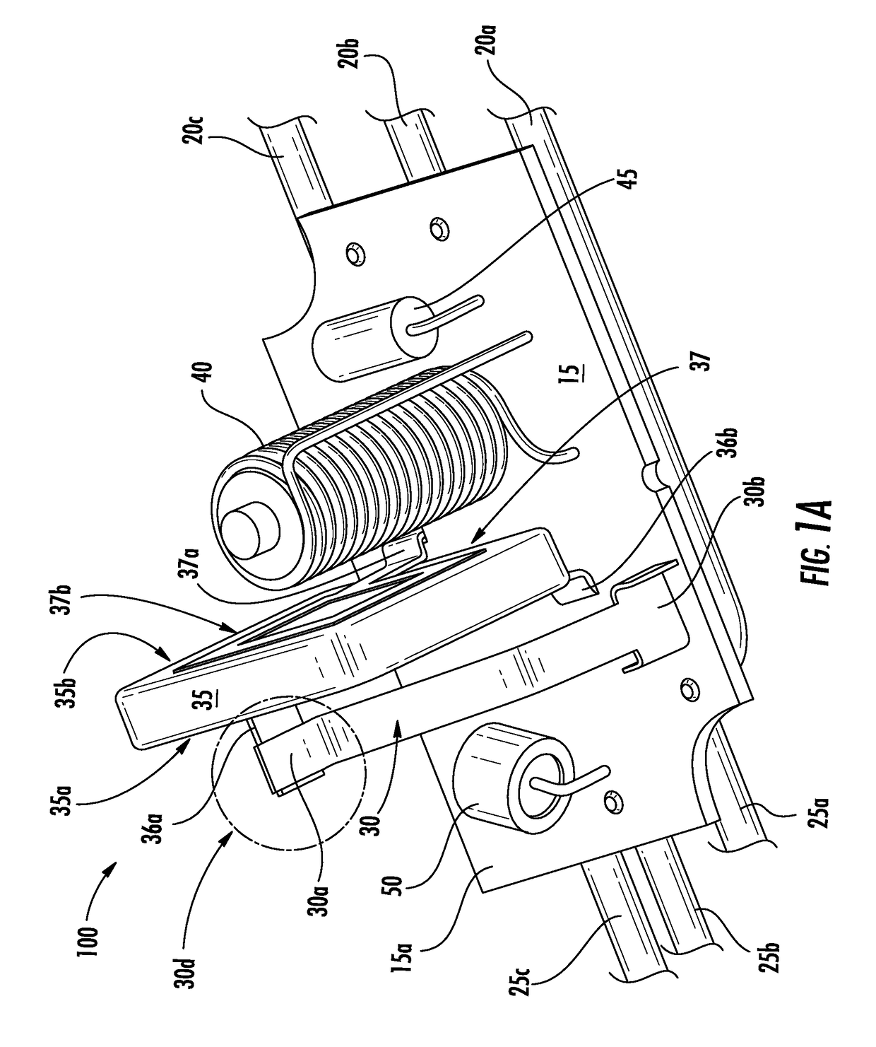
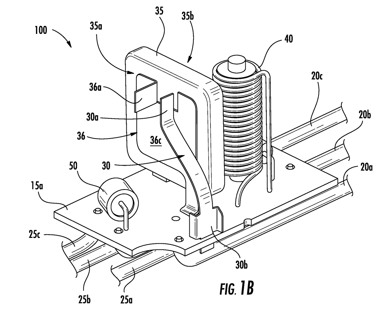
[0023]FIG. 1A is a perspective view of various components of a circuit protection device 100 under normal operating conditions (i.e., where an overvoltage condition does not exist). The circuit protection device 100 includes three input lines 20a, 20b, and 20c and three output lines, 25a, 25b, and 25c. The input line 20a may be a load line connected to a conductive spring terminal 30 at an end 30b having one of a variety of configurations, such as a t-shape. The end 30b of conductive spring...


PUM


Abstract

A circuit protection device includes a metal oxide varistor (MOV), a spring terminal and a thermal disconnect coupling the spring terminal to the MOV. A gas discharge tube (GDT) is coupled to the MOV. The spring terminal is biased such that upon occurrence of an overvoltage condition, heat generated by the MOV melts the thermal disconnect and allows the spring terminal to be displaced away from the MOV, thereby creating an opening circuit.

Description

FIELD OF THE DISCLOSURE[0001]The present disclosure relates to the field of circuit protection devices. More particularly, the present disclosure relates to a surge protection device including a metal oxide varistor.BACKGROUND OF THE DISCLOSURE[0002]Overvoltage protection devices can be used to protect electronic circuits and components from damage due to overvoltage fault conditions. These overvoltage protection devices may include metal oxide varistors (MOVs) that can be connected between the circuits to be protected and a ground line. MOVs have current-voltage characteristics that allow them to be used to protect such circuits against catastrophic voltage surges. These devices may utilize a thermal link that melts during an overvoltage condition to contribute to the formation of an open circuit. In particular, when a voltage is applied to an MOV that is larger than the nominal or threshold voltage of the MOV, then a current can flow through the MOV that generates heat that can ca...

Claims


Application Information

Patent Timeline
Patent Type & Authority Applications(United States)
IPC IPC(8): H02H3/02H01C7/12H01C1/14H01C1/08
CPCH02H3/025H01C7/12H01C1/14H01C1/08H01C7/126H01T1/14H02H3/085H01H2037/763H01H37/761
Inventor YANG, WENTANG, HAILANGXIAO, YANJING
Owner DONGGUAN LITTELFUSE ELECTRONICS CO LTD
Why Eureka
Try Eureka