Engine having shearing resistance reduction patterns

a technology of shearing resistance and reduction pattern, which is applied in the field of engines, can solve the problems of reducing the efficiency of the engine, machining time, and difficult to adjust the productivity of mass production, and achieves the effects of reducing the loss of shearing resistance (friction force), reducing the contribution rate of fuel efficiency, and maximally reducing the contact area

Inactive Publication Date: 2018-03-08
HYUNDAI MOTOR CO LTD
View PDF3 Cites 2 Cited by
  • Summary
  • Abstract
  • Description
  • Claims
  • Application Information

AI Technical Summary

Benefits of technology

[0011]Various aspects of the present invention are directed to providing an engine having shearing resistance reduction patterns capable of greatly increasing a contribution rate of improvement in fuel efficiency based on a Stribeck curve by maximally reducing a contact area by machining a texturing pattern having an optimized pattern shape and a pattern density in a contact section between a cylinder bore and a piston, in particular, maximally reducing a shearing resistance (friction force) loss using a middle section of a cylinder bore.

Problems solved by technology

The loss is directly connected with fuel efficiency and therefore causes a reduction in efficiency of the engine.
However, the laser method and the fly cutting method take excessive machining time to form the groove and therefore are very hard to adjust productivity in mass production.
Above all, the laser method and the fly cutting method has a problem in that the machining portion of the groove is limited to the top section in the entire section of the cylinder bore to make the effect of reducing the loss due to the shearing resistance (friction force) very small.

Method used


Image

  • Engine having shearing resistance reduction patterns
  • Engine having shearing resistance reduction patterns
  • Engine having shearing resistance reduction patterns

Examples


Embodiment Construction

[0030]Reference will now be made in detail to various embodiments of the present invention(s), examples of which are illustrated in the accompanying drawings and described below. While the invention(s) will be described in conjunction with exemplary embodiments, it will be understood that the present description is not intended to limit the invention(s) to those exemplary embodiments. On the contrary, the invention(s) is / are intended to cover not only the exemplary embodiments, but also various alternatives, modifications, equivalents and other embodiments, which may be included within the spirit and scope of the invention as defined by the appended claims.

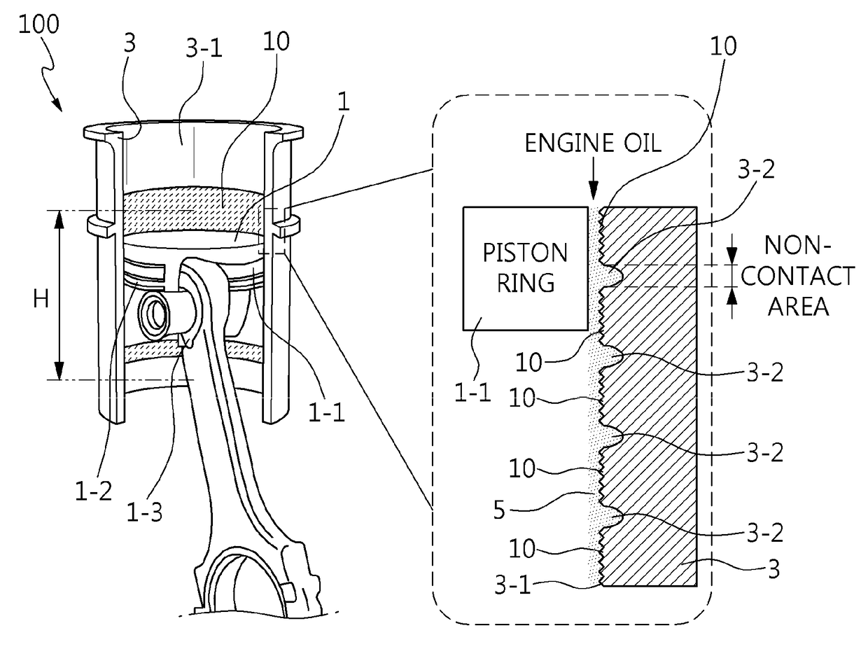
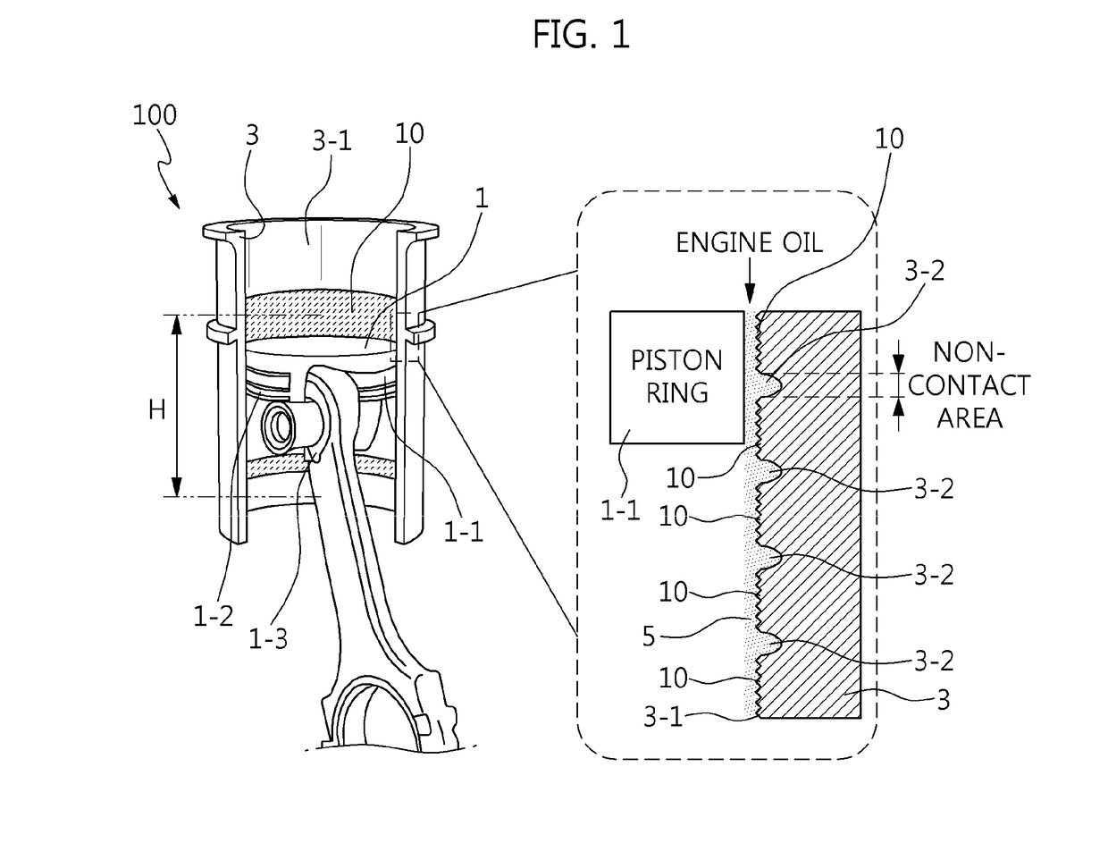
[0031]Referring to FIG. 1, an engine 100 includes a piston 1 generating an output with a vertically reciprocating stroke upon combustion, a liner 3 formed with a cylinder bore 3-1 forming a contact surface to the piston 1, and a texturing pattern 10 reducing a shearing resistance of the contact surface with shearing resistance red...


PUM


Abstract

An engine may include a cylinder bore configured to have a combustion chamber formed by setting a top section in which a top dead center is formed, a bottom section in which a bottom dead center is formed, and a middle section H formed between the top section and the bottom section and reduce a shearing resistance by a texturing pattern formed in the middle section H.

Description

CROSS-REFERENCE(S) TO RELATED APPLICATIONS[0001]The present application claims priority to Korean Patent Application No. 10-2016-0115483, filed Sep. 8, 2016, the entire contents of which is incorporated herein for all purposes by this reference.BACKGROUND OF THE INVENTIONField of the Invention[0002]Exemplary embodiments of the present invention relate to an engine, and more particularly, to an engine with improved fuel efficiency by shearing resistance reduction patterns formed on an inner surface of a cylinder bore.Description of Related Art[0003]Recently, an engine has coped with strengthened laws and fuel efficiency regulations at home and abroad by reducing a contact area between a cylinder bore and a piston based on Newton's law of viscosity to reduce a loss caused by a shearing resistance (friction force).[0004]A cylinder bore and a piston are portions that are first ignited and cause friction within the engine. Here, a piston ring attached to the piston vertically reciprocati...

Claims


Application Information

Patent Timeline
Patent Type & Authority Applications(United States)
IPC IPC(8): F02F1/20
CPCF02F1/20F02F1/00F02F1/004F16J10/04
Inventor PARK, JUN-SIKMIN, SUN-JOONKIM, HEE-GONELEE, NAM-DOOKIM, HO-HWANAN, TAE-KYUNLEE, SEUNG-YEOPKIM, DO-HYUNGLEE, TAE-WON
Owner HYUNDAI MOTOR CO LTD
Why Eureka
Try Eureka