Aircraft vapour trail control system

a control system and vapour trail technology, applied in process and machine control, instruments, navigation instruments, etc., can solve the problems of increasing fuel burn, reduce engine instantaneous contrail factor, reduce engine efficiency, and reduce fuel-efficiency

Active Publication Date: 2015-10-08
ROLLS ROYCE PLC
View PDF0 Cites 21 Cited by
  • Summary
  • Abstract
  • Description
  • Claims
  • Application Information

AI Technical Summary

Benefits of technology

[0017]The controller may vary the thrust produced by each engine so as to balance the thrust contribution by one or more engine on opposing sides of the aircraft.
[0018]The invention beneficially allows the efficiency of the engines to be reduced in order to reduce the instantaneous contrail factor for the engine, whilst ensuring that the aircraft thrust requirements are met.
[0019]The controller may be arranged to determine a maximum available variation in thrust value and / or engine efficiency available for each of the plurality of engines, and an efficiency value and / or range of values required to prevent contrail formation. The controller may be arranged to alter thrust levels and / or engine efficiency only if it is determined that contrail suppression can be achieved thereby. Although engine efficiency exerts a relatively weak effect on contrail formation, it has been found that this effect beneficially provides sufficient scope under certain conditions to enable an aircraft to remain contrail-free at its current / desired flight-level, for example whilst traversing a region of ice-supersaturated air, rather than needing to descend or climb a full 1000 ft or 2000 ft to the next available flight-level, which may correspond to a materially less fuel-efficient cruising altitude. Thus the invention may beneficially reduce the need to alter other aspects of engine operation and / or flight path to mitigate against contrail formation.

Problems solved by technology

However, in addition to the added complexity for air traffic control and pilots, the re-routing of aircraft away from predetermined flight paths will cause increased fuel burn, not only by increasing duration and distance traveled, but also by causing departure from optimal cruise conditions of the aircraft engines.

Method used


Image

  • Aircraft vapour trail control system
  • Aircraft vapour trail control system
  • Aircraft vapour trail control system

Examples


Embodiment Construction

[0047]In essence this invention achieves a contrail suppression effect by selectively altering the total efficiency of each engine, thus decreasing the threshold ambient temperature below which a contrail can form, at a given level of ambient humidity.

[0048]That is to say, when contrail suppression is operative, the contrail formation requires colder ambient air and so takes place under a smaller range of circumstances. The invention may thus act to selectively reduce the contrail factor for the engine.

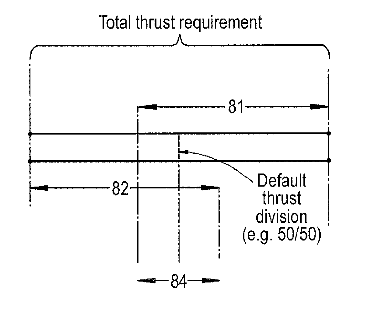
[0049]In varying the total efficiency of each engine, the thrust produced by each engine is varied and so the invention relies on varying the thrust distribution across a plurality of propulsive engines of an aircraft in order to ensure a total aircraft thrust requirement is met. An aircraft having two, three, four or more engines can be accommodated by the invention.

[0050]In the examples defined below, a ‘cost’ parameter or associated function is used for assessment of a contrail sup...


PUM


Abstract

The invention concerns an aircraft propulsion control system in which multiple gas turbine engines (10) are under the control of a controller (30). One or more sensor is arranged to sense a condition indicative of vapour trail formation by an exhaust flow from one or more of the engines. The controller (30) is arranged to be responsive to a thrust demand (51) for the aircraft and to control the thrust produced by each of the engines (10) concurrently so as to alter the efficiency of the engines upon sensing of the vapour trail formation condition, while satisfying the aircraft thrust demand. The controller (30) may output a separate throttle control signal (35) to each engine (10).

Description

BACKGROUND OF THE INVENTION[0001]The present invention relates to aircraft propulsion systems, and more particularly to control systems for aiding the prevention of contrail formation.[0002]Contrails, also known as condensation trails or vapour trails, are line-shaped ice-clouds that appear behind aircraft under certain circumstances. The formation of a contrail depends on a number of factors, including: ambient temperature, humidity and pressure; the efficiency of the aircraft's engines; and the properties of the fuel burned in the engines.[0003]The term “contrail factor” is used to refer to the gradient of a line representing the mixing of engine exhaust air with ambient air, when plotted on a chart using water-vapour partial pressure as the y-axis and temperature as the x-axis. A reduction in an engine's contrail factor reduces the range of ambient conditions under which the engine can form a contrail. Alternatively, at a particular ambient condition (characterised by pressure, t...

Claims


Application Information

Patent Timeline
Patent Type & Authority Applications(United States)
IPC IPC(8): B64D31/10F02C9/00
CPCB64D31/10F02C9/00F05D2270/051F05D2270/08F05D2270/335F05D2220/323F02C9/42F05D2270/13F05D2270/0831Y02T50/60F02C9/28F05D2270/083F05D2270/05
Inventor SWANN, PETER
Owner ROLLS ROYCE PLC
Why Eureka
Try Eureka