
Refrigeration purge system

Active Publication Date: 2018-03-08
CARRIER CORP
View PDF3 Cites 11 Cited by
  • Summary
  • Abstract
  • Description
  • Claims
  • Application Information

AI Technical Summary

Benefits of technology

The patent describes a refrigeration system that uses a membrane to remove contaminants from a purge gas that is collected from a purge outlet in the system. The membrane allows the refrigerant to pass through while the contaminants are blocked. The system also includes a prime mover to move the purge gas from the purge outlet to an exhaust port outside the system. The purge gas can be collected in a purge gas collector and then returned to the system. The system can be controlled based on a cooling demand signal and can include a heat source in thermal communication with the membrane. The technical effects of the system include improved purge gas quality, reduced contamination, and improved system efficiency.

Problems solved by technology

As a result, leaks in the chiller system may draw air into the system, contaminating the refrigerant.
This contamination degrades the performance of the chiller system.
Existing purge units are complicated and lose refrigerant in the process of removing contamination.

Method used


Image

  • Refrigeration purge system
  • Refrigeration purge system
  • Refrigeration purge system

Examples


Embodiment Construction

[0032]A detailed description of one or more embodiments of the disclosed apparatus and method are presented herein by way of exemplification and not limitation with reference to the Figures.

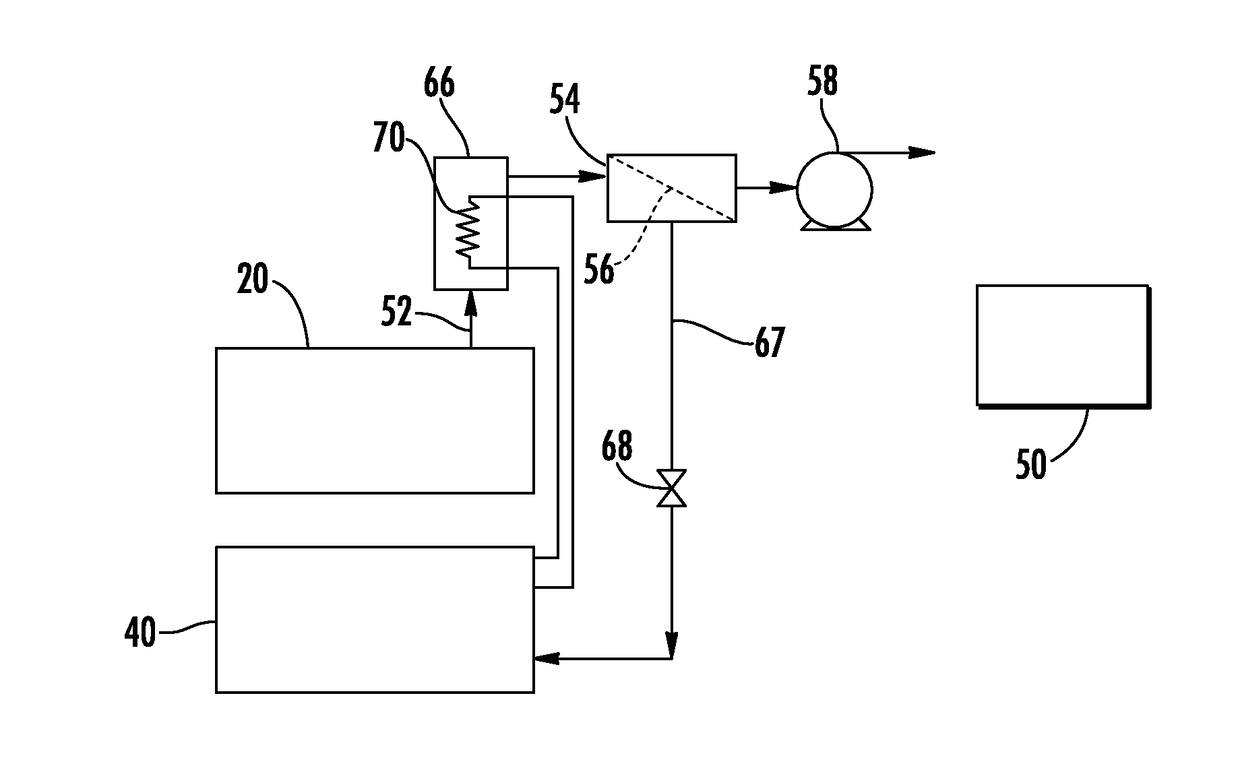
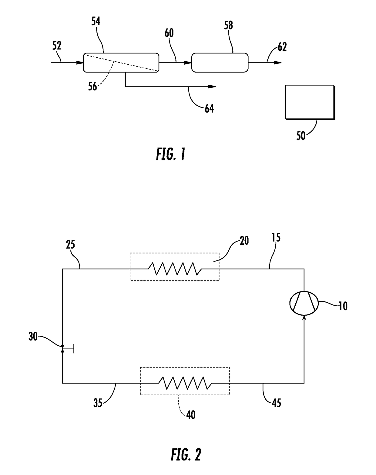
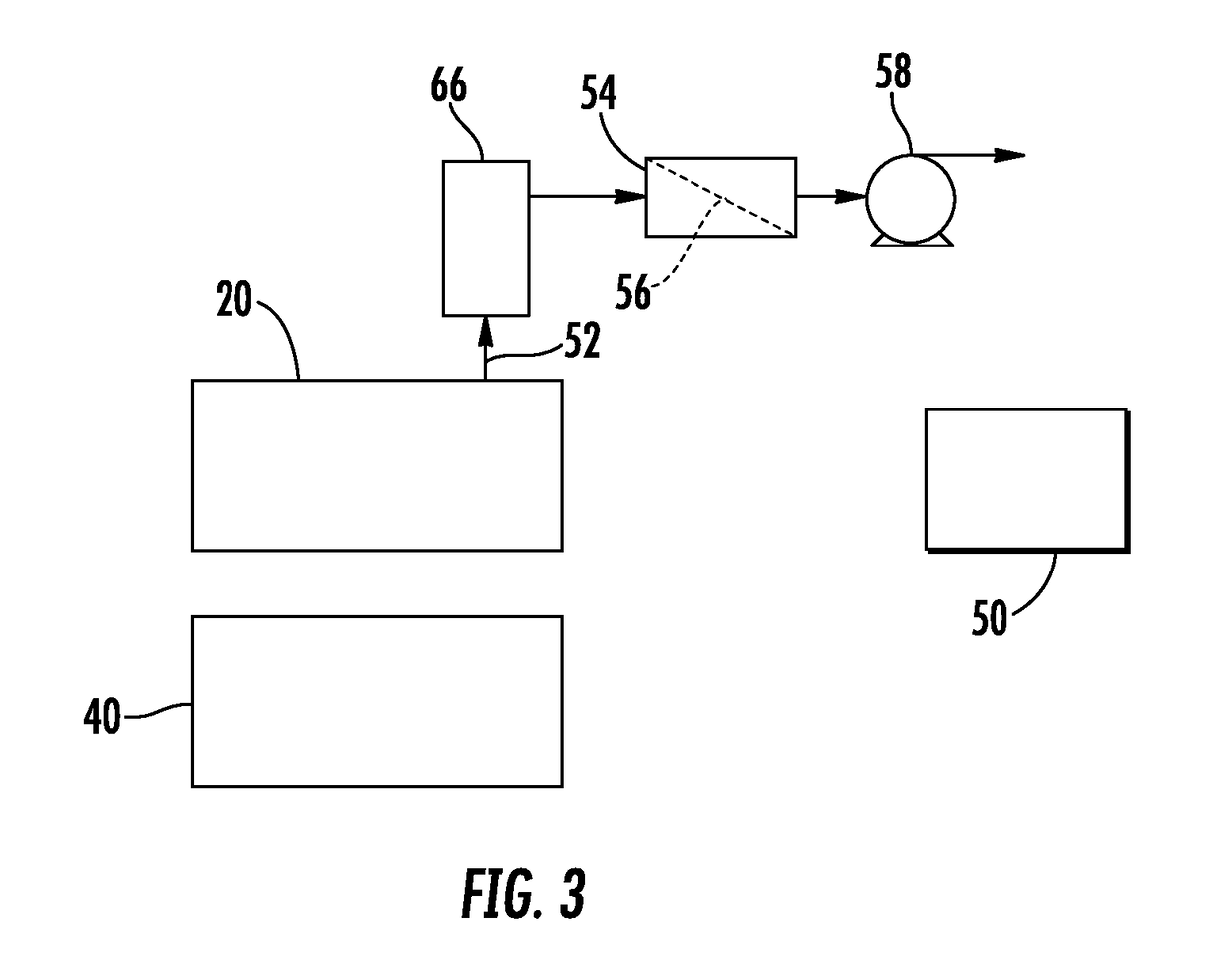
[0033]With reference now to FIG. 1, there is shown an example embodiment of a purge system that can be connected to a heat transfer fluid circulation loop such as the one shown in FIG. 2. As shown in FIG. 1, the purge system receives gas comprising refrigerant gas and contaminants (e.g., nitrogen, oxygen, or water) from a refrigerant-containing refrigeration system such as shown in FIG. 12 through a purge connection 52 to a membrane separator 54 on a first side of a membrane 56. In some embodiments, the contaminants can comprise a non-condensable gas such as components of atmospheric air (e.g., nitrogen, oxygen). A prime mover such as a vacuum pump 58 connected to the membrane separator 54 through connection 60 provides a driving force to pass the contaminant molecules through the membrane 56 and...


PUM


Abstract

Disclosed is a refrigeration system including a heat transfer fluid circulation loop configured to allow a refrigerant to circulate therethrough. A purge gas outlet is in operable communication with the heat transfer fluid circulation loop. The system also includes at least one gas permeable membrane having a first side in operable communication with the purge gas outlet and a second side. The membrane includes a porous inorganic material with pores of a size to allow passage of contaminants through the membrane and restrict passage of the refrigerant through the membrane. The system also includes a permeate outlet in operable communication with a second side of the membrane.

Description

[0001]This is a continuation-in-part of U.S. patent application Ser. No. 14 / 909,542, which is a national stage of PCT / US2014 / 040795, which claims priority to U.S. application Ser. No. 61 / 864,133, the disclosures of each of which is incorporated herein by reference in its entirety.BACKGROUND[0002]This disclosure relates generally to chiller systems used in air conditioning systems, and more particularly to a purge system for removing contaminants from a refrigeration system.[0003]Chiller systems such as those utilizing centrifugal compressors may include sections that operate below atmospheric pressure. As a result, leaks in the chiller system may draw air into the system, contaminating the refrigerant. This contamination degrades the performance of the chiller system. To address this problem, existing low pressure chillers include a purge unit to remove contamination. Existing purge units use a vapor compression cycle to separate contaminant gas from the refrigerant. Existing purge ...

Claims


Application Information

Patent Timeline
IPC IPC(8): F25B43/04F25B43/00
CPCF25B43/043F25B43/003B01D19/0031B01D53/22B01D2311/103
Inventor RANJAN, RAJIVCORDATOS, HARALAMBOSDARDAS, ZISSIS A.ZAFIRIS, GEORGIOS S.FENG, YINSHANVERMA, PARMESHSTARK, MICHAEL A.
Owner CARRIER CORP
Features
  • Generate Ideas
  • Intellectual Property
  • Life Sciences
  • Materials
  • Tech Scout
  • Unparalleled Data Quality
  • Higher Quality Content
  • 60% Fewer Hallucinations
Learn More