Detection apparatus and method for noise intensity and coherent optical receiver
a detection apparatus and noise intensity technology, applied in the field of optical communication technologies, can solve problems such as the limited transmission performance of a system, and achieve the effect of efficient spli
- Summary
- Abstract
- Description
- Claims
- Application Information
AI Technical Summary
Benefits of technology
Problems solved by technology
Method used
Image
Examples
embodiment 1
[0043]The embodiment of this disclosure provides a detection method for noise intensity, applicable to a coherent optical receiver.
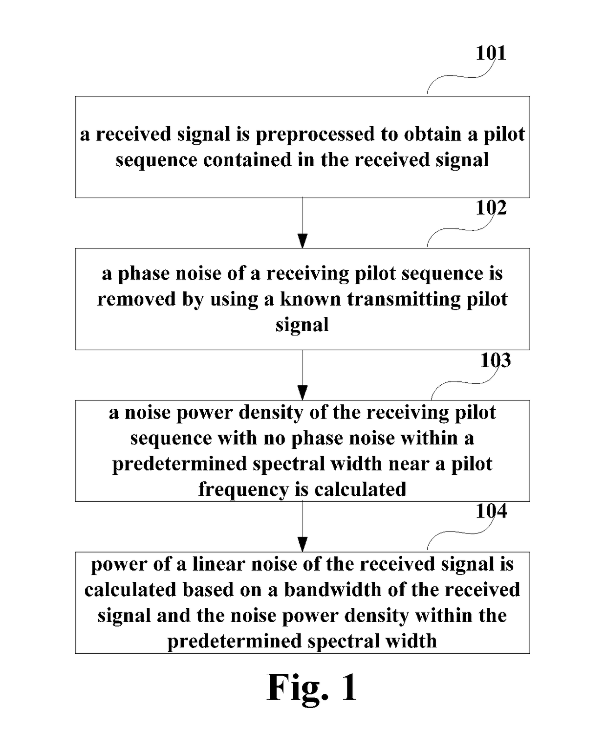
[0044]FIG. 1 is a flowchart of the detection method for noise intensity of Embodiment 1 of this disclosure. As shown in FIG. 1, the detection method for noise intensity includes:
[0045]step 101: a received signal is preprocessed to obtain a pilot sequence contained in the received signal;
[0046]step 102: a phase noise of a receiving pilot sequence is removed by using a known transmitting pilot signal;
[0047]step 103: a noise power density of the receiving pilot sequence with no (or without) phase noise within a predetermined spectral width near a pilot frequency is calculated; and
[0048]step 104: power of a linear noise of the received signal is calculated based on a bandwidth of the received signal and the noise power density within the predetermined spectral width.
[0049]In this embodiment, a pilot sequence may be added into a transmitting signal in a trans...
embodiment 2
[0087]The embodiment of this disclosure provides a detection apparatus for noise intensity, configured in a coherent optical receiver. Contents in this embodiment identical to those in Embodiment 1 shall not be described herein any further.
[0088]FIG. 9 is a schematic diagram of the detection apparatus for noise intensity of the embodiment of this disclosure. As shown in FIG. 9, the detection apparatus 900 for noise intensity includes:
[0089]a signal preprocessing unit 901 configured to preprocess a received signal to obtain a pilot sequence contained in the received signal;
[0090]a phase noise removing unit 902 configured to remove a phase noise of a receiving pilot sequence by using a known transmitting pilot signal;
[0091]a power density calculating unit 903 configured to calculate a noise power density of the receiving pilot sequence with no phase noise within a predetermined spectral width near a pilot frequency; and
[0092]a linear noise calculating unit 904 configured to calculate ...
embodiment 3
[0108]The embodiment of this disclosure provides a coherent optical receiver, which may be configured with the detection apparatus 900 or 1000 for noise intensity described in Embodiment 2. Contents in this embodiment identical to those in embodiments 1 and 2 shall not be described herein any further.
[0109]FIG. 11 is a schematic diagram of the coherent optical receiver of the embodiment of this disclosure. As shown in FIG. 11, the coherent optical receiver 1100 may include:
[0110]an optical-to-electrical converter 1101 configured to convert a received optical signal into an electrical signal; and
[0111]a digital signal processor 1102 configured to preprocess the electrical signal to obtain a pilot sequence contained in the electrical signal, remove a phase noise of a receiving pilot sequence by using a known transmitting pilot signal, calculate a noise power density of the receiving pilot sequence with no phase noise within a predetermined spectral width near a pilot frequency, and ca...
PUM
 Abstract
Description
Claims
Application Information
 - R&D
- Intellectual Property
- Life Sciences
- Materials
- Tech Scout
- Unparalleled Data Quality
- Higher Quality Content
- 60% Fewer Hallucinations
Browse by: Latest US Patents, China's latest patents, Technical Efficacy Thesaurus, Application Domain, Technology Topic, Popular Technical Reports.
© 2025 PatSnap. All rights reserved.Legal|Privacy policy|Modern Slavery Act Transparency Statement|Sitemap|About US| Contact US: help@patsnap.com


