
Methods And System For Controlling A Combination Boiler

Active Publication Date: 2018-03-15
LOCHINVAR
View PDF7 Cites 15 Cited by
  • Summary
  • Abstract
  • Description
  • Claims
  • Application Information

AI Technical Summary

Benefits of technology

The invention described in the patent text may offer a solution to the problems mentioned earlier. Its technical effect may be to address the problems in a more effective way, enhancing the efficiency and effectiveness of the invention.

Problems solved by technology

Current combination boiler implementations experience difficulty managing the time it takes after a hot water draw is started to supply water at a desired temperature.
In cases where the required DHW flow is less than the minimum setting of the flow switch, the boiler will not fire and there the unit will not provide heated water.
Because of the use of thermostatic mixing valves with combination boilers, it is not advisable to implement a hot water circulation system where the full circulation (and / or recirculation) flow passes through a combination boiler.
This makes it impractical to achieve flows high enough to trigger a flow switch of the combination boiler.
Providing pre-heat functionality in a combination boiler presents numerous challenges.
One such challenge relates to avoiding frequent firing cycles and short run times for a combination boiler, which would otherwise cause problematic thermal cycling of the primary combustion heat exchanger and potentially reduce the lifecycle of the boiler.
For example, if a pre-heat method is scheduled at 5:00 A.M., the pre-heat method does not help if a DHW demand occurs at 4:30 A.M. Other pre-heat methodologies rely on firing the boiler at specific time intervals.
However, periodic firing does not allow for hot water circulation (and / or recirculation) or low flow DHW draws.

Method used


Image

  • Methods And System For Controlling A Combination Boiler
  • Methods And System For Controlling A Combination Boiler
  • Methods And System For Controlling A Combination Boiler

Examples


Embodiment Construction

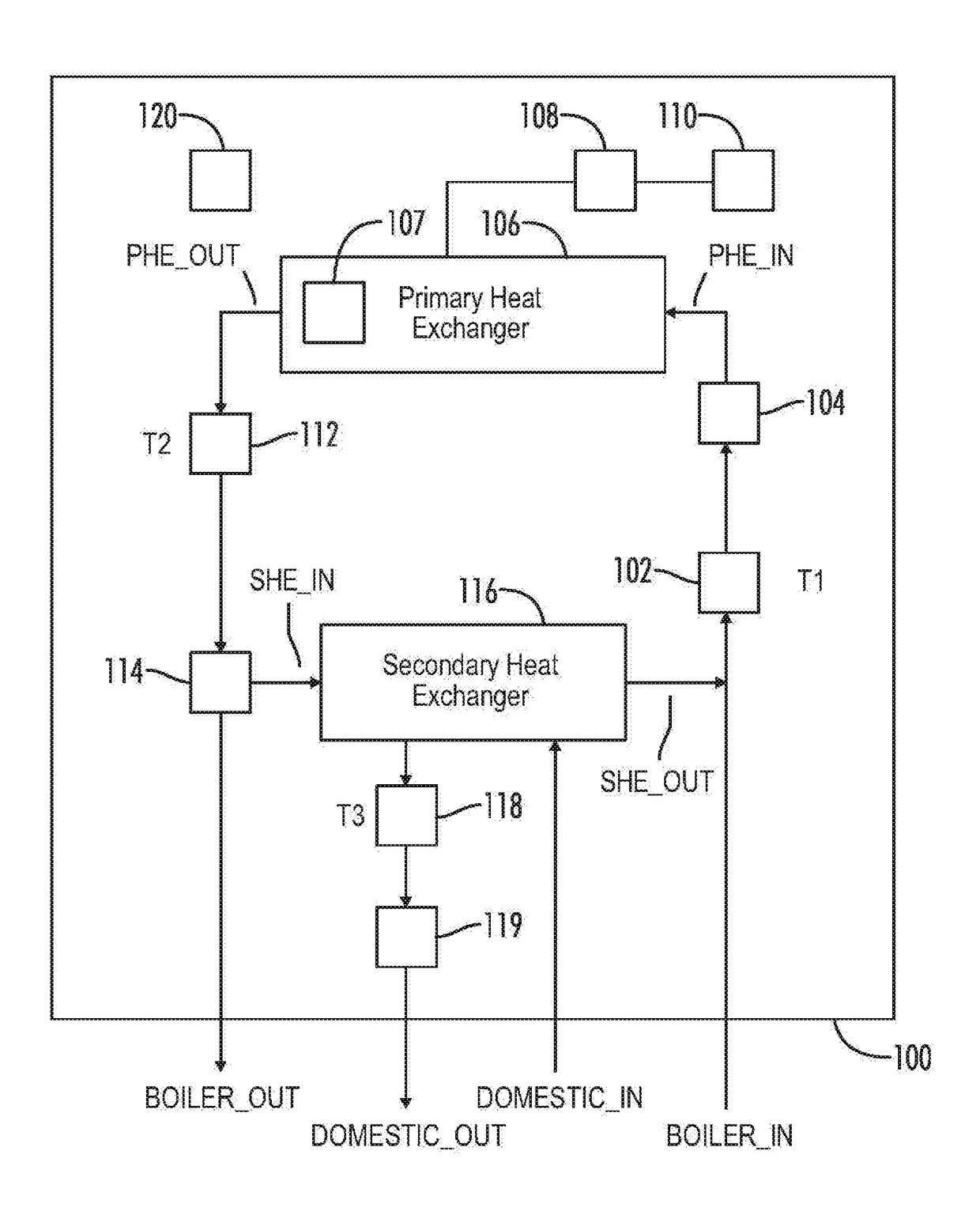
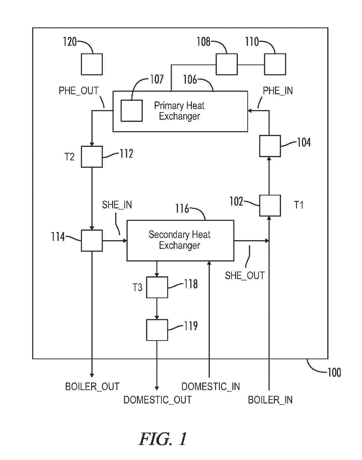
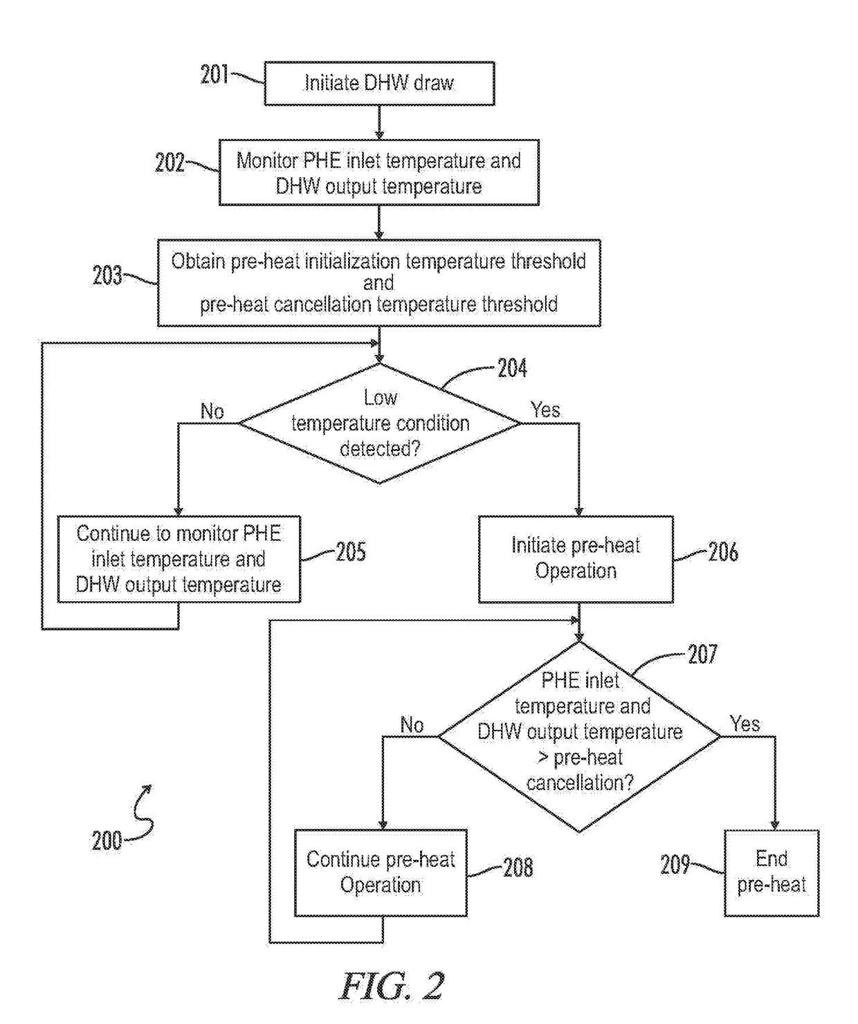
[0033]Referring generally to FIGS. 1-18, various exemplary embodiments of an invention may now be described in detail. Where the various figures may describe embodiments sharing various common elements and features with other embodiments, similar elements and features are given the same reference numerals and redundant description thereof may be omitted below.

[0034]Various embodiments disclosed herein are directed to methods and systems for controlling a combination boiler. Exemplary implementations consistent with the present disclosure may reduce the time required to provide hot water at a desired water temperature by, for example, maintaining boiler loop water stored in a primary heat exchanger of a combination boiler at an elevated temperature in order to be able to start transferring heat immediately when a hot water demand is started but before the boiler can be fired. Implementations consistent with the present disclosure may also identify when a low flow condition associated...


PUM


Abstract

A combination boiler provides heated water to a boiler loop and domestic hot water (DHW) to a domestic water loop. The combination boiler includes a primary heat exchanger (PHE) connected to the boiler loop and a burner to provide heat to the primary heat exchanger. A secondary heat exchanger (SHE) transfers heat energy from the boiler loop to the domestic water loop. A controller monitors a PHE inlet temperature and a DHW output temperature, obtains a pre-heat initialization temperature threshold and a pre-heat cancellation temperature threshold, and detects a low temperature condition. A pre-heat operation is initiated responsive to the low temperature condition by circulating heated water from the PHE to the SHE. The burner is selectively fired at least in part according to an outlet temperature of the PHE.

Description

[0001]A portion of the disclosure of this patent document contains material that is subject to copyright protection. The copyright owner has no objection to the reproduction of the patent document or the patent disclosure, as it appears in the U.S. Patent and Trademark Office patent file or records, but otherwise reserves all copyright rights whatsoever.CROSS-REFERENCES TO RELATED APPLICATIONS[0002]This application claims benefit of the following patent application(s) which is / are hereby incorporated by reference: NoneSTATEMENT REGARDING FEDERALLY SPONSORED RESEARCH OR DEVELOPMENT[0003]Not ApplicableREFERENCE TO SEQUENCE LISTING OR COMPUTER PROGRAM LISTING APPENDIX[0004]Not ApplicableBACKGROUND OF THE INVENTION[0005]The present invention relates generally to controlling operations of a combination boiler. More particularly, the present invention relates to providing a combination boiler control to reduce an amount of time it takes to reach a desired temperature for a domestic hot wa...

Claims


Application Information

Patent Timeline
IPC IPC(8): F24D19/10F24D3/08
CPCF24D19/1069F24D3/08F24D2240/10F24D2220/06F24D2220/042F24H1/52F24H1/124F24H9/2035F24H15/219F24H15/486F24H15/36F24H15/215F24H15/174F24H15/269F24H15/414
Inventor GAGNE, CURTIS GEORGE
Owner LOCHINVAR
Learn More