EGR cooling and condensate regulation system for natural gas fired co-generation unit

a technology of condensate regulation and natural gas, which is applied in the direction of machines/engines, mechanical equipment, and non-fuel substance addition to fuel, etc., can solve the problems of not providing adequate incentives for industry entities to construct generating facilities, the failure of traditional energy producers to replace spent units and capitalize new plants, and the inability of alternative energy producers to achieve the effects of reducing nox emission, reducing unwanted condensation, and increasing efficiency of natural gas fired co/generation systems

Inactive Publication Date: 2005-12-27
CHAPEAU
View PDF13 Cites 67 Cited by
  • Summary
  • Abstract
  • Description
  • Claims
  • Application Information

AI Technical Summary

Benefits of technology

[0033]It has now been unexpectedly discovered that the use of at least one air-to-gas condensing cooler, downstream of a primary exhaust gas air-to-gas cooler, allows increased efficiency of a natural gas fired co / generation system through out the load range, while cooling cylinder combustion temperatures, reducing unwanted condensation within the intake manifold, and controlling propagation to effect a reduced NOx emission at increased efficiency. The instant EGR cooling system allows EGR recycle rates above 10% by achieving a superior level of controlled EGR cooling and water vapor regulation (>900° F. exhaust reduced to <130° F.) as compared to existing gas-to-air heat exchanger designs.
[0036]Advantageously, the exhaust gas exiting the second unit enters a condensation storage / removal unit prior to entering the engine intake air stream. In this manner, the water vapor condensed can be removed from the recycle system and discarded or reused, for example, as a further cooling medium or it can be reintroduced into the engine intake manifold to regulate the temperature and / or performance of the engine.
[0039]An exemplary exhaust gas cooling and condensate regulation system of the instant invention cools exhaust gas entering the first air-to-gas cooling unit is about 925° F. and said system exhaust gas exiting the at least one second air-to-gas cooling unit is less than 130° F. In another embodiment, a separate intercooler circuit is used to cool the compressed intake charge containing the recycled gas prior to entry into the intake engine manifold to further reduce head temperatures and control thermal NOx emissions.

Problems solved by technology

There are a number of reasons for this, but chief among them is failure of traditional energy producers to replace spent units and capitalize new plants.
In addition, new challenges face electric generation-security.
These alternatives, however, have their own problems.
Unfortunately, the deregulation process has not provided adequate incentives for industry entities to construct generating facilities, upgrade the transmission grid, or provide consumers with price signals to enable intelligent demand-side management of energy consumption.
However, swings in supply and demand leave end users open to fluctuations in the cost of electricity.
Despite California's highly publicized energy situation, a similar problem exists for other states as well; the New York Independent System Operator recently stated that 8600 MW of additional generating capacity (a 25 percent increase) must be added by 2005 to avoid widespread shortages that may lead to blackouts.
In addition to the mismatch between demand and generating capacity, the physical transmission infrastructure necessary to deliver power from geographically remote generating facilities to the consumer's location is unable to support the increased load.
Even under today's operating conditions, the transmission grid is subject to stress and occasional failure.
The potential market for distributed generation has become vast without adequate means for fulfilling this need.
Again, inefficiency, reliability, and environmental concerns are major barriers.
In the case of power generation, the waste heat is not used, and the economics are based largely on the cost of the electricity produced (i.e. heat rate is paramount), with little consideration for improved reliability or independence from the electric grid.
The impediment to widespread use is reliability, convenience, and trouble-free operation.
Unfortunately, to date, the most widespread and cost-effective technologies for producing distributed generation and heat require burning hydrocarbon-based fuel.
Unfortunately, the emissions associated with burning hydrocarbon fuels are generally considered damaging to the environment and the Environmental Protection Agency has consistently tightened emissions standards for new power plants.
Green house gases, as well as entrained and other combustion product pollutants, are environmental challenges faced by hydrocarbon-based units.
However, many of the markets that would be best served by the economics of engine-based co-generation have such poor air quality that strict exhaust emission limits have been instituted by air quality regulating agencies.
The exhaust emissions limits on oxides of nitrogen, carbon monoxide, and non-methane hydrocarbons are so restrictive that no technology exists to allow raw exhaust emissions from any engine operating on any hydrocarbon fuel to enter the atmosphere without exhaust aftertreatment and a variety of other strategies. problem area is the emissions produced by these natural gas engines.
Each approach has undesirable consequences compared to the original excess-air, or lean-burn, operation.
This scenario also results in reduced fuel efficiency compared to a lean-burn engine.
Thus, applying SCR technology is expensive, complicated, and generally not considered an option for engines producing less than one megawatt of electric power.
Prior art co-generation systems employing internal combustion engines, and specifically, natural gas fueled engines, have suffered from the myriad of problems including elevated head temperatures and inability to deliver large quantities of process and / or utility heat not true to the co-generation client.
Excessive head temperatures lead to inefficient operation and unacceptable environmental conditions, which include excessive use of fuel as well as significant thermal NOx production.
Although the prior art systems have had the desired effect of reducing nitrogen oxides in the exhaust by reducing the maximum combustion temperature as a consequence of diluting the fuel-air mixture with recycled exhaust gases during certain operating conditions of the engine, these systems have not been experienced broad market application in the field of cogeneration where continuously high engine output is the normal mode of operation and the level technological implementation on engine controls often lacks the automotive market.
Any incremental increase in rate of cooled EGR applied during combustion at any load results in lower peak combustion temperatures and hence lower untreated NOx emissions.
While there are numerous products available commercially for the accurate control and metering of the amount of excess-air used in traditional lean-burn (lambda>1) engines, the same is not true for recirculated exhaust gas metering and cooling in non-automotive applications.
The industrial nature of the cogeneration market does not benefit from the research and development budgets of the mass produced automotive products and thus the application of advanced emissions control techniques such as cooled EGR has thus far been limited.
One challenges for applying EGR highly loaded natural gas engines includes is to provide sufficient cooling of the recirculated exhaust gas such that impacts on volumetric efficiency of air induction are minimized.
The higher the temperature of the recirculated exhaust gas as it enters the air / fuel stream, the more difficult it becomes to induce adequate air flow to support full load combustion.
Specifically, the EGR system did not recycle exhaust gas to the intake engine manifold at sufficiently low temperature to foster low cylinder head temperatures.
This combination of disadvantages made natural gas fueled, internal combustion driven co-generation systems a marginal candidate for client based distributed generation complexes.
Thus, cooling of the gas in a non-regulated manner can present condensation problems in the intake venturi.
If the gas is cooled in the EGR cooler, so that the vapor pressure in the exhaust gas approaches saturation, further cooling by introduction of air and fuel causes an immediate condensation within the intake manifold, which can lead to erratic engine performance, corrosion, and the like.
In addition, the presence of large amounts of water vapor in the recycled exhaust gas displaces other combustion gases in the intake manifold making the engine unstable.
Problematically, introducing the recycle gas at a temperature above the dew point (to prevent induction condensation) leads to detonation and NOx production causing the engine to burn out of NOx emission ranges as well as shorting engine life.
However, in addition to being hard to “tune”, large primary coolers are expensive because they must handle very high temperatures and corrosive media.
Because the volume of very hot gas varies as the engine accelerates or decelerates, the water vapor in the exhaust gas exiting such primary coolers, is difficult to regulate.
When the cooler is a single unit, it is difficult to incrementally vary the composition of the output gas.
This inherently limits the minimum EGR temperature that can be achieved to well over 200° F. even with the best of liquid-to-gas heat exchangers.
This design is very expensive, but necessary to handle the exhaust gas heat.
In addition, certain spark ignited engines, such as gasoline and natural gas fueled engines, have different EGR constraints than compression ignition engines, such as diesel.
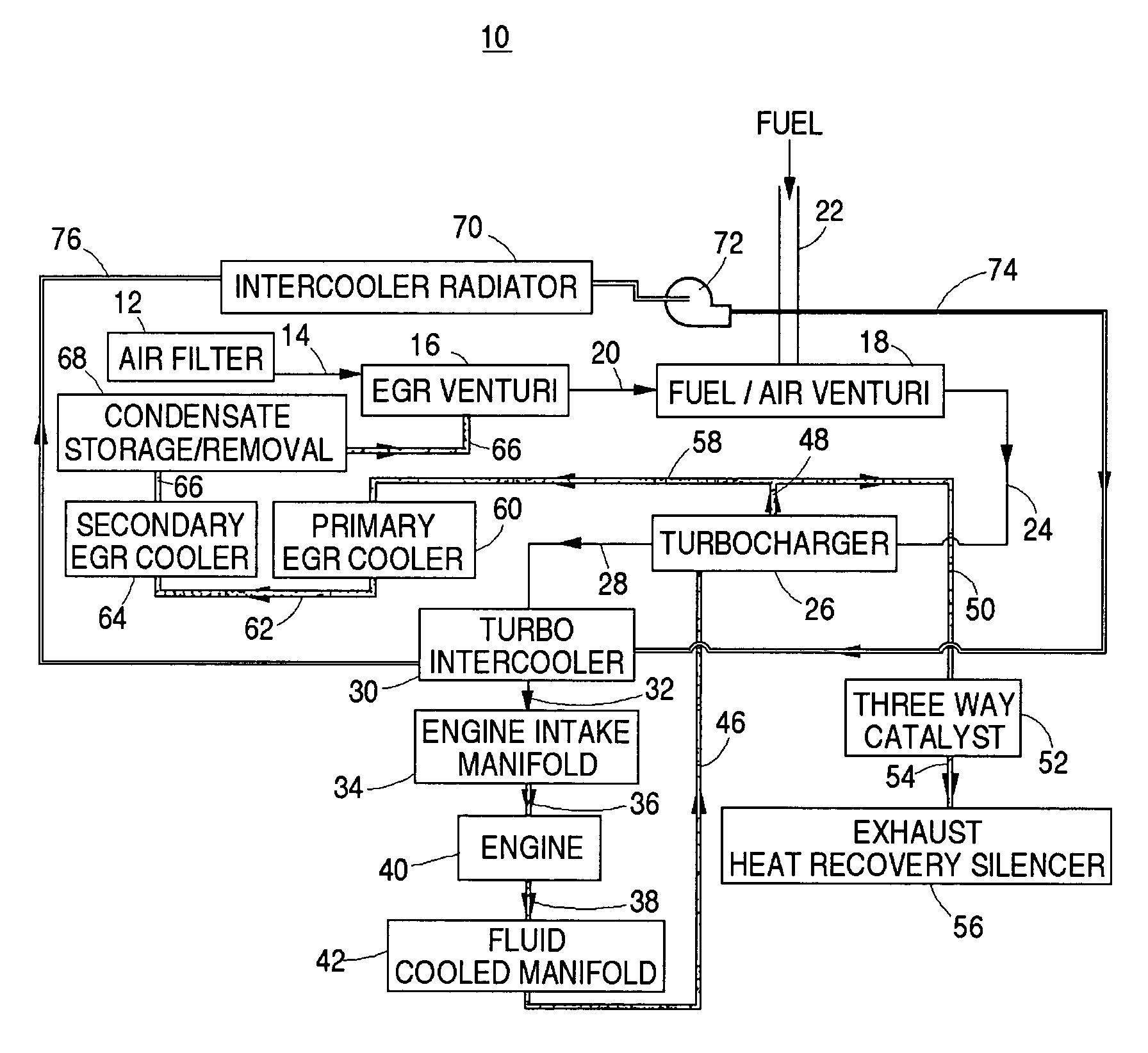
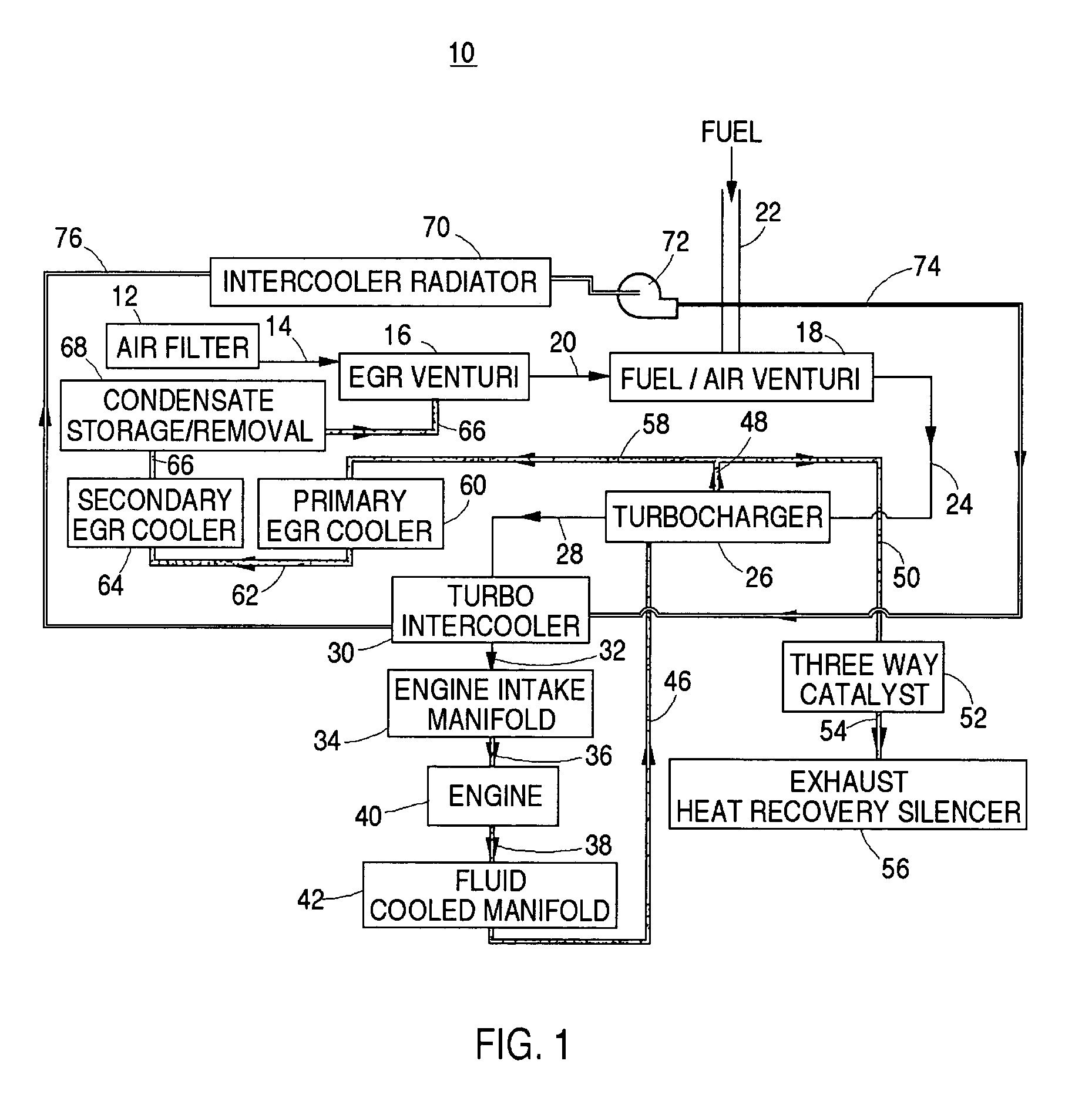
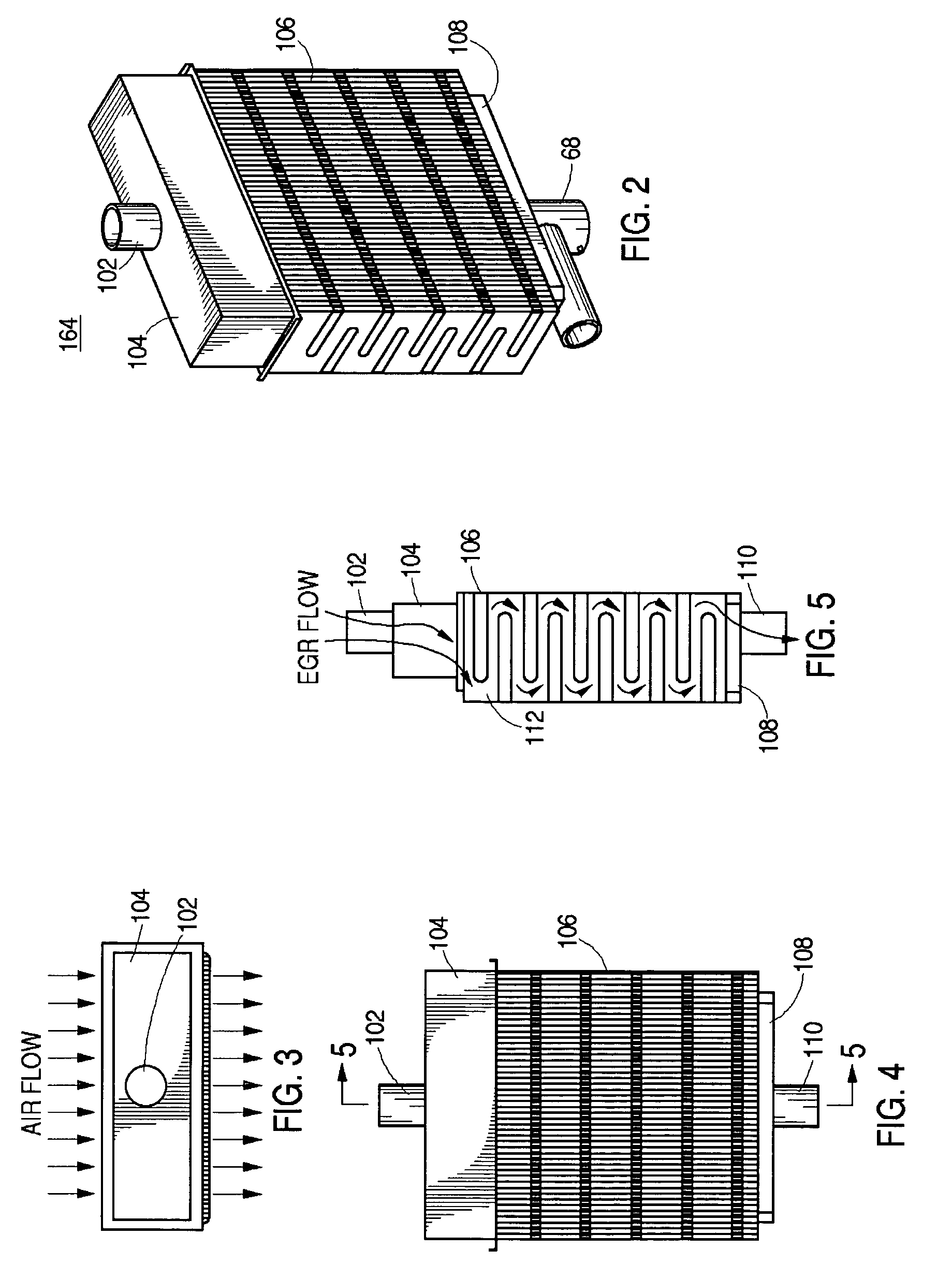
Method used


Image

  • EGR cooling and condensate regulation system for natural gas fired co-generation unit
  • EGR cooling and condensate regulation system for natural gas fired co-generation unit
  • EGR cooling and condensate regulation system for natural gas fired co-generation unit

Examples


Embodiment Construction

[0047]In accordance with the instant invention, a natural gas fueled, internal combustion engine, employing exhaust gas recycle (EGR), delivers power to spin a coupled electric turbine, as well as heat of combustion, through a heat exchanger, to a co-generation process / utility heat loop for on site use as heat for process water, utility heat, space heat, potable hot water, and the like. This is accomplished with the instant system by increasing the transfer of engine heat to the co-generation process / utility heat loop while maintaining the engine, and especially the cylinder combustion temperature low enough to increase efficiency and reduce thermal NOx to acceptable levels, even in the presence of the recycled exhaust gas. This is accomplished with substantially no increase in parasitic power requirements, such as adding external pumps to increase the flow through the heat exchanger and decreased necessity for catalytic exhaust system clean up.

[0048]As air is inducted into the cyli...


PUM


Abstract

A recycled exhaust gas cooling and condensate regulation system for a natural gas fired internal combustion engine driven co-generation plant, which allows efficient exhaust recycled gas combustion while maintaining lower head temperatures to reduce thermal NOx emissions and delivering increased process / utility heat to a proximate co-generation client, is provided. The recycled exhaust gas cooling and condensate regulation system has primary and secondary, air-to-gas, exchanger units, coupled in series, such that the first unit, designed to take exhaust gas exiting the engine, cools the gas to a first exhaust gas temperature effectively super saturating the water vapor in the cooled exhaust gas; and, the second unit, designed to handle lower inlet temperatures, condenses the water vapor and super cools the exhaust gas to <130 F. In one embodiment, the engine intake mixture including the exhaust gas is supercharged. In another embodiment, a separate intercooler circuit is used to cool the compressed intake charge containing the recycled gas prior to entry into the intake engine manifold to further reduce head temperatures and control thermal NOx emissions.

Description

CROSS-REFERENCE TO RELATED APPLICATION[0001]The present application is a Continuation-in-Part of U.S. application Ser. No. 10 / 361,538 filed Feb. 10, 2003 for “Fuel Regulator for Natural Gas Fired Co-Generation”, now U.S. Pat. No. 6,748,932, and is a U.S. application Ser. No. 10 / 838,126 filed May 3, 2004, which is a Continuation of U.S. application Ser. No. 10 / 356,826 filed Feb. 3, 2003 for “Heat Transfer System for Co-Generation Unit” now U.S. Pat. No. 6,729,133, all of said applications are herein incorporated by reference in their entirety.BACKGROUND OF THE INVENTION[0002]1. Field of the Invention[0003]The present invention relates generally to recycled exhaust gas cooling systems for natural gas fueled internal combustion engines; and, more particularly, to systems for controlling temperature and condensate in cooled exhaust gas for recycle to natural gas fueled internal combustion engines to effect engine operating characteristics and emission control.[0004]2. Description of Rel...

Claims


Application Information

Patent Timeline
Patent Type & Authority Patents(United States)
IPC IPC(8): F01N3/02F01N3/04F01N5/02F02B29/04F02B37/00F02M21/02F02M25/07
CPCF02M25/0732F02M25/0736F02M25/074F02M21/0215F01N3/046F01N5/02F01N2240/02F02B29/0406F02B37/00F02M25/0707F02M25/0722Y02T10/121Y02T10/32F02M26/05F02M26/19F02M26/24F02M26/31F02M26/35Y02T10/30
Inventor DORN, GERALD R.ROSER, RANSON R.
Owner CHAPEAU
Why Eureka
Try Eureka