Standalone flow rate controller for controlling flow rate of cooling or heating fluid through a heat exchanger

a flow rate controller and heat exchanger technology, applied in the direction of temperatue control, process and machine control, instruments, etc., can solve the problems of over-capacity of selected units, increased humidity, and difficulty in accurately matching the heating or cooling capacity of the device to the load, so as to save pump energy and improve the performance of fluid heating and cooling devices.

Inactive Publication Date: 2009-12-24
AKZ TECH
View PDF22 Cites 65 Cited by
  • Summary
  • Abstract
  • Description
  • Claims
  • Application Information

AI Technical Summary

Benefits of technology

[0007]In accordance with the invention there is provided an improved load-matched flow control valve device that can be utilized for improved performance of fluid heating and cooling devices while saving pump energy at the same time.

Problems solved by technology

A drawback associated with conventional flow control valves is the difficulty in accurately matching the heating or cooling capacity of the device to the load it sees from the space it has to condition.
But generally heating engineers design for worst-case conditions, as a result of which under normal (i.e. non-worst conditions) the selected unit is over-capacity.
This is why in conventional installations people freeze in the summer and swelter in the winter.
Another problem with conventional flow control valves is that failure to reduce the cooling capacity of a coil results in increased humidity and a greater chance of mold and mildew developing.
Furthermore, control devices based on refrigerant pressure require access to the refrigerant.
This can result in refrigerant leaks damaging the equipment and the environment and requires a separate valve for each refrigerant.
Such devices are not ideally suitable for improving the performance of fluid heating and cooling devices while saving pump energy at the same time.

Method used


Image

  • Standalone flow rate controller for controlling flow rate of cooling or heating fluid through a heat exchanger
  • Standalone flow rate controller for controlling flow rate of cooling or heating fluid through a heat exchanger
  • Standalone flow rate controller for controlling flow rate of cooling or heating fluid through a heat exchanger

Examples


Embodiment Construction

[0021]In the following description of some embodiments, identical components that appear in more than one figure or that share similar functionality will be referenced by identical reference symbols.

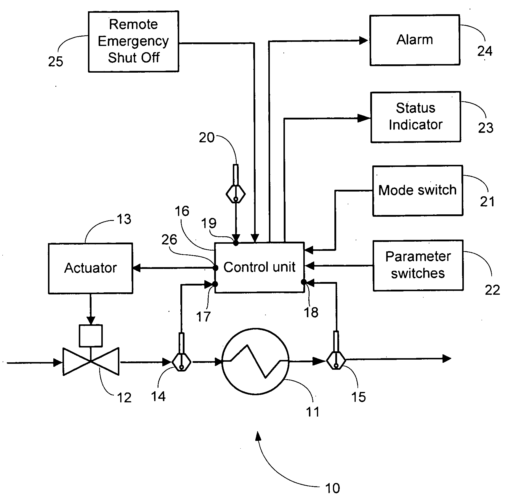
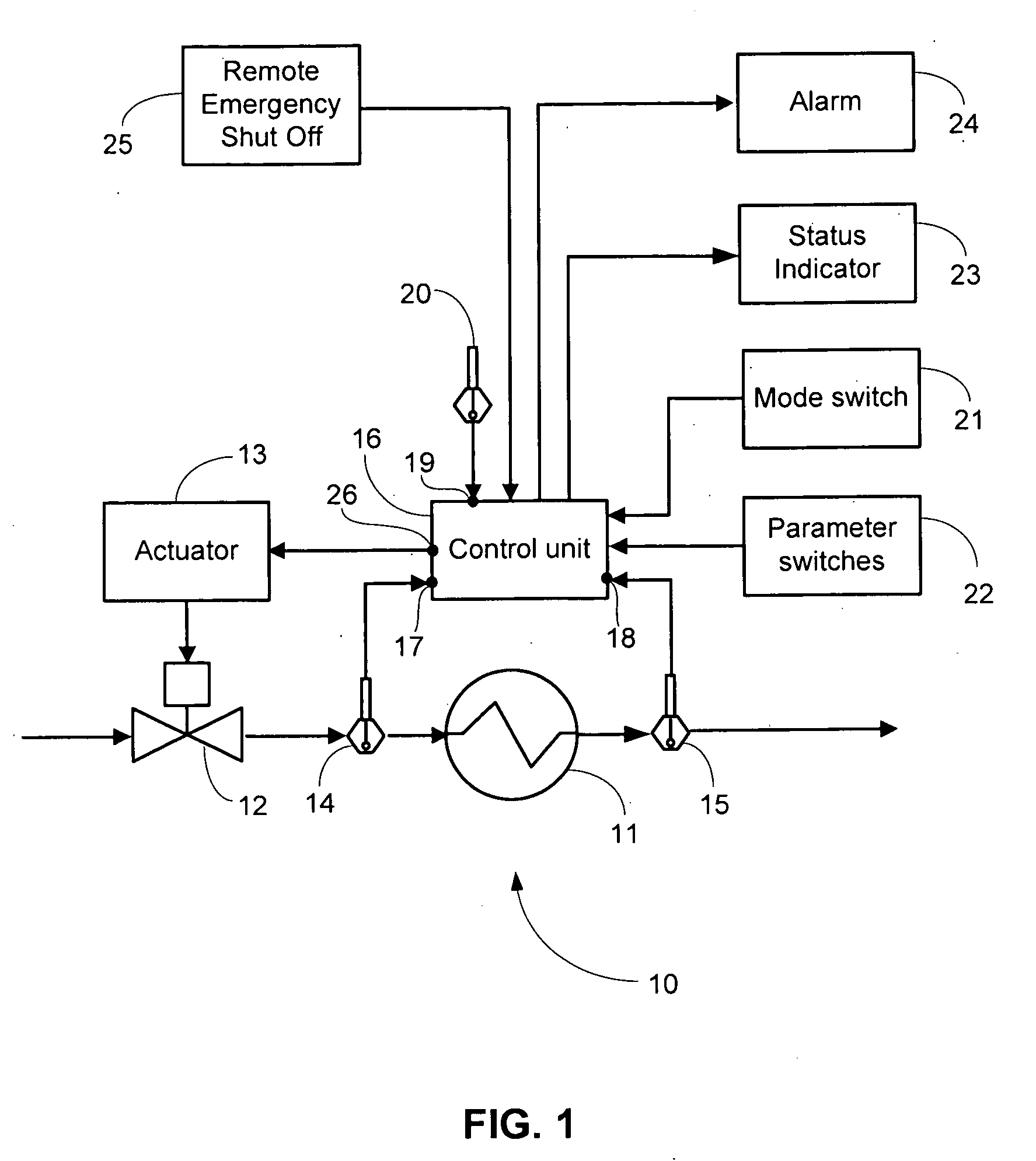
[0022]FIG. 1 shows schematically a heating / cooling system 10 comprising a heat exchanger 11 coupled to a fluid load-matched flow control valve 12 that is actuated via an actuator 13. The heat exchanger 11 has an input pipe through which cold or hot water flows to which heat is either input from the environment or from which heat is extracted to the environment. This may be done using either a fan coil or a water source heat pump. Fluid flow through the heat exchanger 11 is assumed to be from left to right as denoted via an arrow. In accordance with the invention, a first temperature sensor 14 is attached to the fluid pipe as it enters the heat exchanger 11, and a second temperature sensor 15 is attached to the fluid pipe as it leaves the heat exchanger 11. The valve 12 is controlled by a...


PUM


Abstract

A standalone flow rate controller for controlling flow rate of cooling or heating fluid through a heat exchanger by providing a control signal to a flow valve actuator so as to open or close a flow valve in response thereto. A first temperature sensor measures an entry temperature of the cooling or heating fluid flowing into the heat exchanger and a second temperature sensor measures an exit temperature of the cooling or heating fluid flowing out of the heat exchanger. A control unit is responsive to a temperature difference between the entry temperature and the exit temperature for adjusting the control signal so as maintain the temperature difference substantially constant.

Description

FIELD OF THE INVENTION[0001]The present invention relates generally to flow control valves and more specifically to a load matched flow control valve for improved performance of fluid heating and cooling devices while saving pump energy at the same time.BACKGROUND OF THE INVENTION[0002]Flow control valves that serve to vary fluid flow based on an input from a control device that senses room temperature or refrigerant pressure are well known. Such valves eliminate the need for system flow balancing and reduce main pump energy. Typically such valves operate in a fully open or fully closed state under the control of a thermostat that measures room temperature and provides a control signal for opening or closing the valve. A drawback associated with conventional flow control valves is the difficulty in accurately matching the heating or cooling capacity of the device to the load it sees from the space it has to condition. Space heating or cooling units have a predetermined maximum therm...

Claims


Application Information

Patent Timeline
Patent Type & Authority Applications(United States)
IPC IPC(8): G05D23/00
CPCG05D23/192
Inventor BARRETT, KEVINNILES, ALAN F.
Owner AKZ TECH
Why Eureka
Try Eureka