Spray head and spraying apparatus

a spray head and spraying head technology, applied in the direction of valve arrangements, engine components, venting valves, etc., can solve problems such as damage to the spray head

Active Publication Date: 2018-03-22
HUSQVARNA AB
View PDF5 Cites 4 Cited by
  • Summary
  • Abstract
  • Description
  • Claims
  • Application Information

AI Technical Summary

Benefits of technology

[0005]Advantageously, due to the drip-stop element a slow dripping or running empty of the spray head after the irrigation process is avoided. In addition, the frost resistance is increased because after stopping the irrigation process, liquid included in the spray head is removed from the interior of the spray head. Furthermore, the weight of the shower head is reduced thereby improving the handling of the shower head. Finally, calcification effects and growth of algae are significantly reduced.
[0010]According to embodiments, the drip-stop element comprises a sealing portion providing a sealing between the spray head base body and the nozzle plate. The sealing portion may be a ring-shaped sealing portion forming the outer edge of the drip-stop element. Said sealing portion may be adapted to be arranged between an upper edge of the spray head base body and the nozzle plate in order to seal the spray head circumferentially. The sealing portion may be an integral part of the single-piece drip-stop element. Thereby, additional sealing elements can be avoided.
[0012]According to embodiments, the sealing portion comprises an angular-shaped sealing rim comprising an acute-angled edge or slanted sealing lip, said acute-angled edge or slanted sealing rim interacting with the nozzle plate in order to increase the sealing effect. For example, the acute-angled edge forms a triangular edge which is provided at the top portion of the sealing rim. In case of a slanted sealing lip, said sealing lip may be slanted inwardly. When pressing the nozzle plate onto said acute-angled edge or slanted sealing lip, the top portion of the acute-angled edge, respectively the sealing lip is deformed thereby obtaining a bead which further enhances the liquid tightness between the nozzle plate and the spray head base body.
[0015]According to embodiments, a support element is provided referring to the liquid flow direction in front of the drip-stop element in order to limit the movement of the top portion of the drip-stop element. The support element may comprise one or more support portions formed by one or more protrusions. Said support portions may provide stop portions for limiting the stroke movement of the top portion. Thereby, an undesired overstretching of the drip-stop element is avoided.

Problems solved by technology

In addition, there is the problem that said residual liquid may freeze within the spray head thereby damaging the spray head.

Method used


Image

  • Spray head and spraying apparatus
  • Spray head and spraying apparatus
  • Spray head and spraying apparatus

Examples


Embodiment Construction

[0033]The present invention will now be described more fully with reference to the accompanying drawings, in which example embodiments are shown. However, this invention should not be construed as limited to the embodiments set forth herein. Throughout the following description similar reference numerals have been used to denote similar elements, parts, items or features, when applicable.

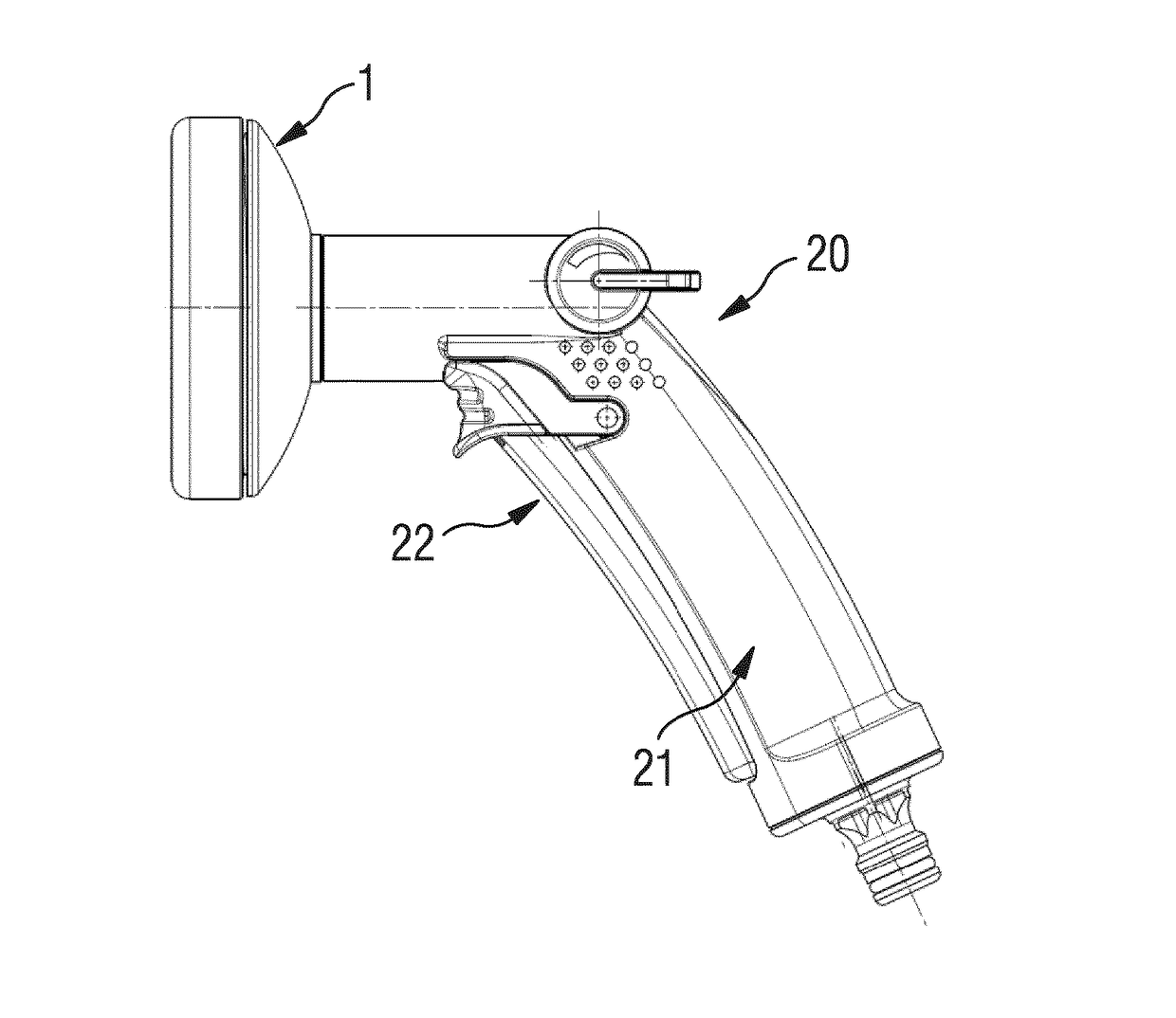
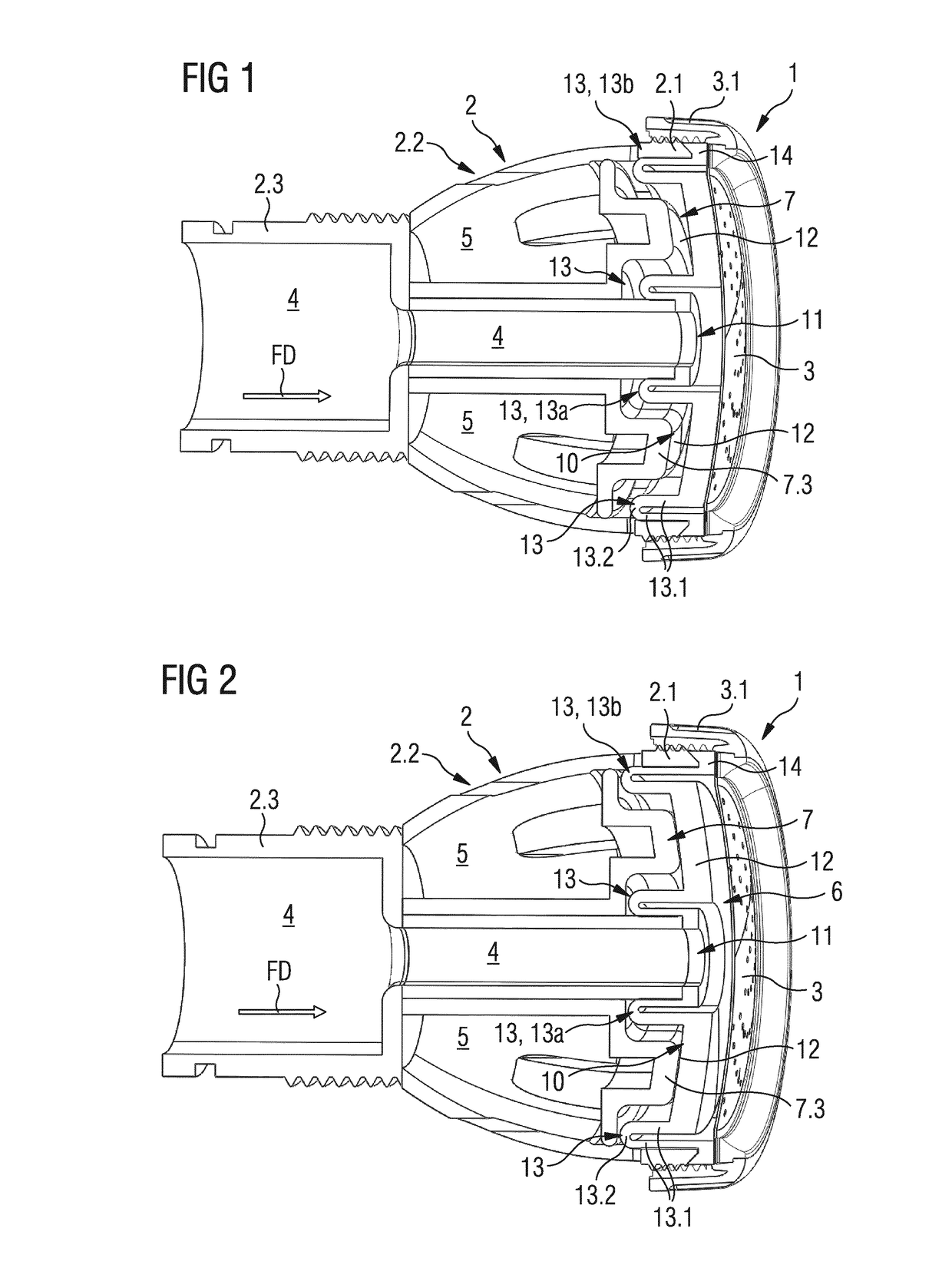
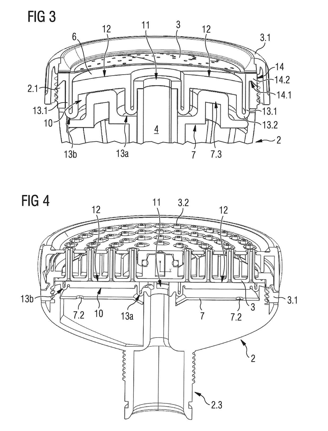
[0034]FIG. 1 shows a spray head 1 being adapted to be used in a spraying apparatus, e.g. a spray gun for supplying water to flowers or plants or a shower head used in bath rooms. The spray head 1 comprises a spray head base body 2 and a nozzle plate 3 being attached to the spray head base body 2 by means of a threaded ring 3.1, i.e. the spray head base body 2 comprises an external thread and the threaded ring 3.1 is adapted to be screwed onto said external thread for securing the nozzle plate 3 at the spray head base body 2. The spray head 1 may further comprise a coupling portion 2.3 for coupling t...


PUM


Abstract

The invention relates to a spray head comprising a spray head base body (2) and a nozzle plate (3), the spray head base body (2) comprising at least one liquid channel (4) for providing a liquid flow towards the nozzle plate (3), wherein a drip-stop element (10) is located between the spray head base body (2) and the nozzle plate (3), said drip-stop element (10) comprising at least one opening (11) being fluidly coupled with said liquid channel (4) for providing a fluid flow into a space (6) between the drip-stop element (10) and the nozzle plate (3), wherein at least a top portion (12) of said drip-stop element (10) is movably mounted within a spray head chamber (5) in order to perform a stroke movement, wherein said top portion (12) is preloaded such that the top portion (12) rests against the nozzle plate (3) without applying any external forces to the top portion (12) and said top portion (12) is lifted off the nozzle plate (3) in case that a liquid flow is provided through the liquid channel (4) into the space (6) between said top portion (12) and the nozzle plate (3).

Description

[0001]The present invention relates generally to the field of spray heads. More specifically, the present invention is related to a spray head including a drip-stop element in order to avoid dripping or running empty of the spray head after stopping the irrigation process.BACKGROUND OF THE INVENTION[0002]Spray heads, specifically spray heads of shower head type, are well-known in prior art. After stopping the irrigation process, spray heads comprising a large shower head diameter include a large amount of residual liquid within the spray head. Due to gravitational force, said residual liquid drops out of the spray head. Said dripping out is noticed by a user as leakage. In addition, there is the problem that said residual liquid may freeze within the spray head thereby damaging the spray head.SUMMARY OF THE INVENTION[0003]It is an objective of the embodiments of the present invention to provide a spray head which avoids residual liquid (specifically water) in the interior of the spr...

Claims


Application Information

Patent Timeline
Patent Type & Authority Applications(United States)
IPC IPC(8): B05B1/18B05B1/30
CPCB05B1/185B05B1/3006F16K24/04B05B1/18B05B1/30B05B11/0044B05B1/323
Inventor RENNER, THOMAS
Owner HUSQVARNA AB
Why Eureka
Try Eureka