Optical System, and Assembly for Emitting Light

a technology of optical system and light source, applied in the direction of instruments, lighting and heating apparatus, planar/plate-like light guides, etc., can solve the problems of significant simplifying the production of the system, and achieve the effects of improving efficiency, facilitating light transfer, and facilitating light transfer

Active Publication Date: 2018-03-22
ZUMTOBEL LIGHTING GMBH & CO KG
View PDF2 Cites 3 Cited by
  • Summary
  • Abstract
  • Description
  • Claims
  • Application Information

AI Technical Summary

Benefits of technology

[0009]Furthermore, as a result of the elongated shape of the lens element, the first optical element can be formed with a comparably large light emission region, via which the light exits the first optical element and then enters the second optical element via the at least one elongated lens element. The efficiency is improved in this manner.
[0010]The at least one elongated lens element preferably has a groove extending parallel to the longitudinal axis, which is configured for light entry and is formed on a side of the second optical element facing toward the first optical element. The light can be transferred particularly effectively through the groove from the first optical element to the second optical element.
[0011]The groove preferably extends in both directions to the edge of the second optical element. This results in a comparatively larger light transfer region, such that it is particularly efficient. Furthermore, the lens element is easier to produce when the groove extends to both ends of the lens element.
[0012]The at least one elongated lens element preferably has diverging outer boundaries in a cross section perpendicular to the longitudinal axis. This shape enables a particularly effective bundling of the light into the other plane.
[0013]The first optical element preferably has at least one elongated structure, parallel to the longitudinal axis, for light emission. This shape makes the first optical element easier to produce. By way of example, the elongated structure can extend in both directions to the edge of the first optical element. Furthermore, a comparatively larger light transfer region is formed between the two optical elements in this manner.
[0014]Preferably, the configuration is such that—when seen in a perpendicular projection onto the plane—the at least one elongated structure and the at least one elongated lens element overlap at least in part, preferably such that the elongated structure lies within the projection of the at least one elongated lens element. In this manner, a particularly low loss light transfer from the first optical element to the second optical element can be obtained with an advantageous use of space.

Problems solved by technology

This results in boundary conditions that significantly simplify production of the system.

Method used


Image

  • Optical System, and Assembly for Emitting Light
  • Optical System, and Assembly for Emitting Light
  • Optical System, and Assembly for Emitting Light

Examples


Embodiment Construction

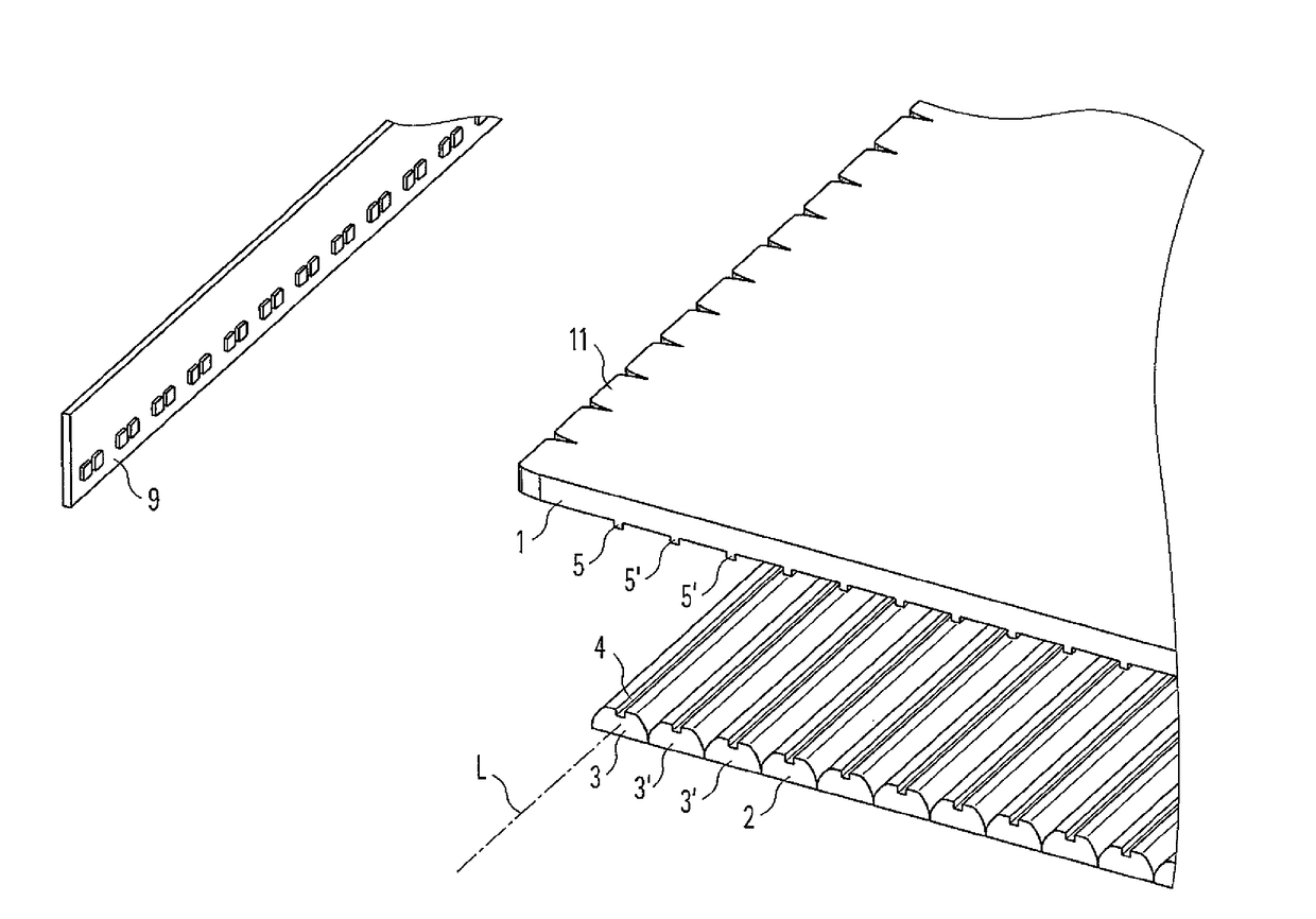
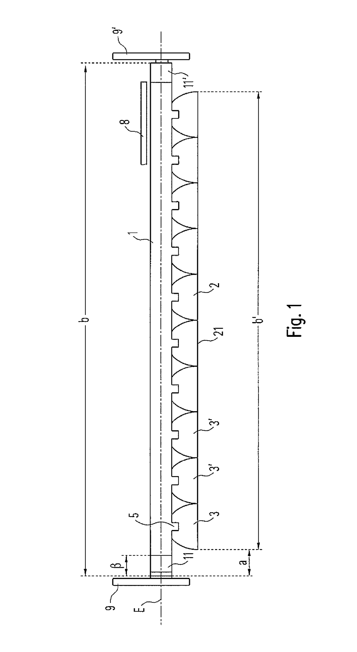
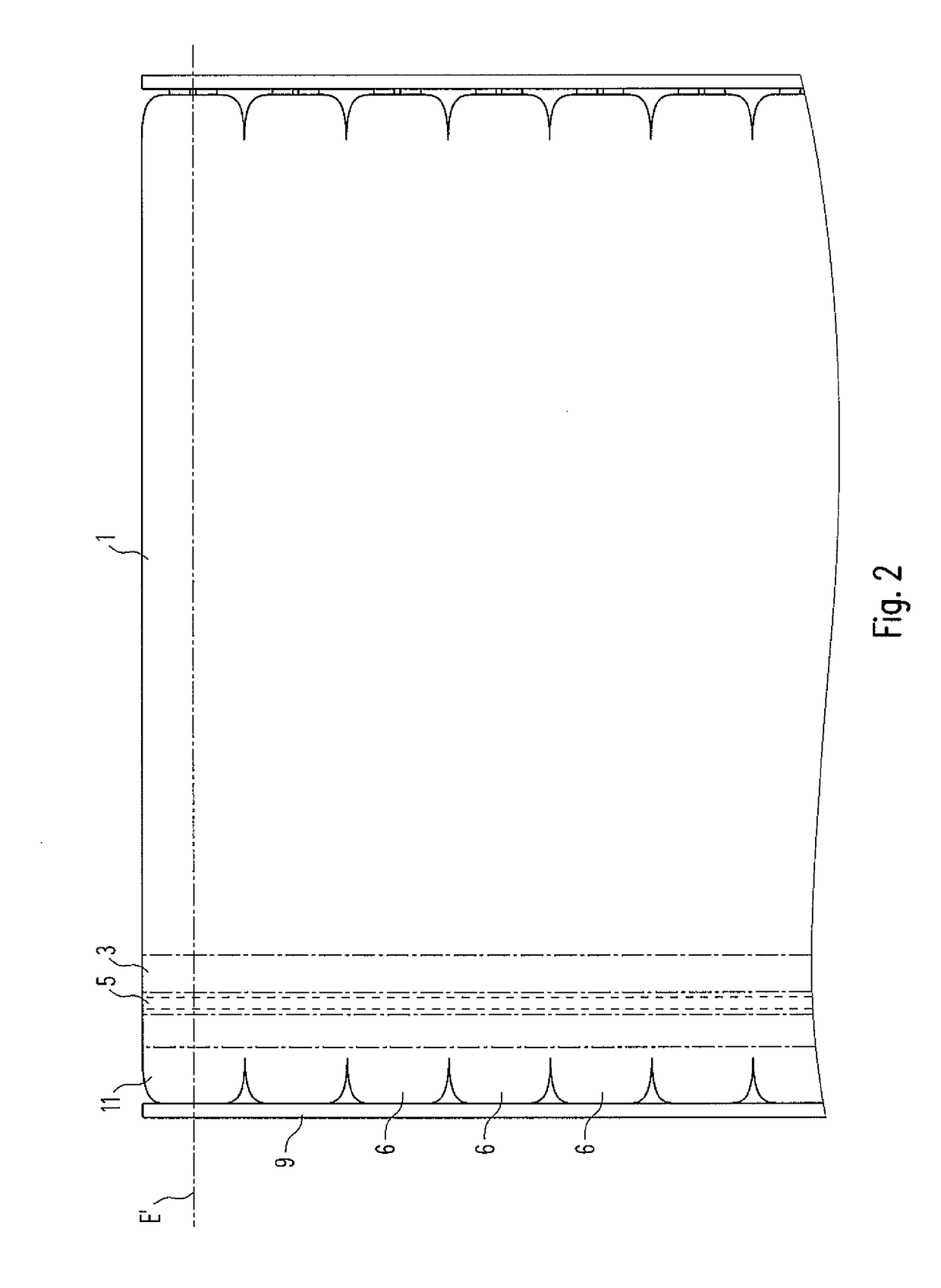
[0033]FIG. 1 shows a cross sectional illustration of an assembly according to the invention for emitting light, FIG. 2 shows an illustration of a top view of a part of the assembly. The assembly comprises an optical system according to the invention, for influencing a light emitted from a light source 9. The light source 9 is part of the assembly according to the invention thereby.

[0034]The optical system comprises a first optical element 1, which is basically plate shaped, such that the plate defines a plane E. In this description, it is assumed that the first optical element 1 is horizontal, and the plane E is accordingly horizontal. In general, however, the assembly can also be operated with other orientations of the first optical element 1 in relation to the vertical axis. In this case, the present directional information, etc. must be reinterpreted.

[0035]FIG. 7 shows a detail of the illustration in FIG. 2. In this example, the light source 9 comprises numerous LEDs 91 disposed ...


PUM


Abstract

An optical system for influencing a light has a first optical element (1), by means of which a plane (E) is defined, wherein the first optical element (1) has a lateral edge region (11) designed for the entry of the light, and a second optical element (2), wherein the second optical element (2) is arranged parallel to the first optical element (1) and has a light outlet region (21) for the exiting of the light. The lateral edge region (11) of the first optical element (1) is designed to reduce the glare of or bundle the light in the plane (E), and the second optical element (2) has a elongate lens element (3), which extends along a longitudinal axis (L) and is designed to reduce the glare of or bundle the light in an additional plan (E′), which is oriented at least substantially perpendicularly to the plane (E) mentioned first.

Description

CROSS REFERENCE TO RELATED APPLICATION[0001]The present application is the U.S. national stage application of International Application PCT / EP2016 / 058207, filed Apr. 14, 2016, which international application was published on Oct. 20, 2016 as International Publication WO 2016 / 166203 A1. The International Application claims priority to German Patent Application 20 2015 101 870.3 filed Apr. 14, 2015.FIELD OF THE INVENTION[0002]The invention relates to an optical system that influences light emitted from a light source, and an assembly for emitting light with such an optical system.BACKGROUND OF THE INVENTION[0003]A lighting system having a substantially plate-shaped waveguide and, likewise a, substantially plate-shaped anti-glare unit is known from DE 10 2012 215 640 A1. The anti-glare unit is disposed parallel to and beneath the waveguide. Furthermore, the lighting system comprises an LED light source (LED: light emitting diode) for generating a light that shines into the waveguide at...

Claims


Application Information

Patent Timeline
Patent Type & Authority Applications(United States)
IPC IPC(8): F21V8/00
CPCG02B6/005G02B6/0045G02B6/0055G02B6/0068G02B6/002F21V5/04G02B6/0011G02B6/0053G02B6/0066G02B6/0073
Inventor MACHATE, ANDREAS
Owner ZUMTOBEL LIGHTING GMBH & CO KG
Why Eureka
Try Eureka