Check patentability & draft patents in minutes with Patsnap Eureka AI!

Signal processing device

Active Publication Date: 2018-03-22
DENSO CORP
View PDF8 Cites 7 Cited by
  • Summary
  • Abstract
  • Description
  • Claims
  • Application Information

AI Technical Summary

Benefits of technology

The present invention provides a signal processing device that can output communication data using different methods without interfering with each other. This is achieved by configuring the device to limit interference among the various communicators during switch operations. This allows the device to use different methods for transmitting data to different destinations without needing separate ICs for each method. Overall, the invention allows a single output terminal to output communication data using different methods without interference.

Problems solved by technology

However, in such case, the switching between the plurality of different functional blocks may cause interference among the different communication methods.
That is, the functional blocks implementing different communication methods may interfere with each other.
When an interference is caused, the power consumption by signal processing circuits may dramatically increase and may lead to a low power source voltage in the ECU supplying power to the signal processing circuits.
Also in such as case, abnormal data may be transmitted from the signal processing circuits, which may cause a deterioration of data reliability and / or cause a malfunction, for example, when the destination ECU cannot read the data.
In such case, the switch controller is configured to set an output state of all of the plurality of communicators to a high impedance state, at least when the switch operation is performed, so that interference among the plurality of communicators implementing different communication methods is limited at the time of the switch operation.

Method used


Image

  • Signal processing device
  • Signal processing device
  • Signal processing device

Examples


first embodiment

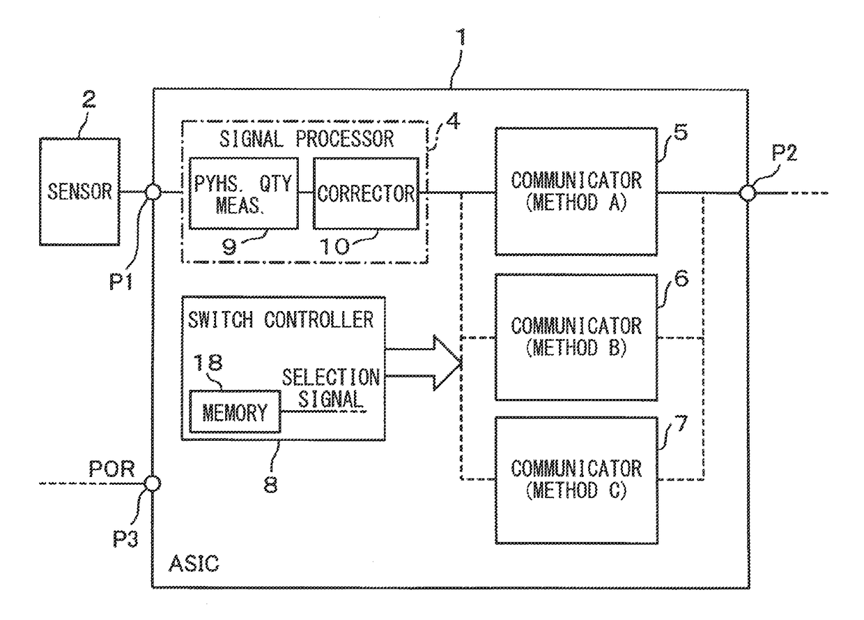
[0027]With reference to FIG. 1, a signal processing device 1 is configured to processes a detection signal from a sensor 2 input through a terminal P1, and to output data after the signal processing (i.e., processed data) at terminal P2 via communication to an ECU 3, as shown in FIG. 2, that is external to the signal processing device 1. The signal processing device 1 may be provided as an Application Specific Integrated Circuit “ASIC.”

[0028]The sensor 2 may be an airflow meter, pressure sensor, vacuum-boost sensor, and the like, measuring the amount of airflow, pressure, vacuum, etc. in and to a vehicle engine.

[0029]The signal processing device 1 is provided with communicators 5-7, a signal processor 4, a switch controller 8, and the like.

[0030]The signal processor 4 is configured to perform preset signal processing to a detection signal output from the sensor 2, and includes a physical quantity measurer 9 and a corrector 10.

[0031]The physical quantity measurer 9 amplifies the dete...

second embodiment

[0074]In the second embodiment, the operation control of the communicators 5-7 by the switch controller 8 is different from the first embodiment. The following description refers not only to FIG. 4 but also to FIG. 1 as to the configuration of the signal processing device.

[0075]The second embodiment also assumes an example situation where the selection signal selects communication method A. That is, as shown in FIG. 4, when the reset signal POR is given at time t0, each of the components of the signal processing device 1 is reset. Under such circumstance, the switch controller 8 controls the communicators 5-7 so that each of the outputs of the communicators 5-7 has the same level, e.g., a high level of 5 V, which may be designated as an “H level.”

[0076]After each of the components is reset, just like the first embodiment, the switch controller 8 reads the selection signal from the memory 18, and selects a communication method based on the selection signal.

[0077]The switch controller...

third embodiment

[0088]As shown in FIG. 5, depending on the communication method, the terminal states (PU, PD, etc.) and the resistance values at communication terminal P21 (as shown in FIG. 7) for an ECU 3 connected to the output terminal P2 via a communication line 20 are different.

[0089]More practically, in an analog voltage output communication (also designated as an “analog output”), the communication terminal P21 may either be in the PU state or in the PD state, and, the resistance value of the terminal P21 is set in a range of 180 kΩ-500 kΩ.

[0090]In a push-pull type SENT communication (also designated as a “SENT push-pull”) and the curve type SENT communication (also designated as “SENT curve”), the communication terminal P21 is in the PU state, and the resistance value is set in a range of 10 kΩ-50 kΩ.

[0091]In a frequency output type communication (also designated as a “frequency output”), the communication terminal P21 is in the PU state, and the resistance value is set to 2.2 kΩ, for examp...


PUM


Abstract

A signal processing device includes a signal processor, a plurality of communicators, and a switch controller. The signal processor performs a preset signal processing for a detection signal that is output from a sensor. The plurality of communicators output communication data from an output terminal after converting data from the signal processor to communication data for different communication methods. The switch controller controls the data output operation of each of the plurality of communicators and then performs a switch operation to validate the data output operation of one of the plurality of communicators based on a selection signal that selects one of the communication methods. The switch controller sets the plurality of communicators to a high impedance output state at least at a time of performing the switch operation.

Description

CROSS REFERENCE TO RELATED APPLICATION[0001]The present application is based on and claims the benefit of priority of Japanese Patent Application No. 2016-181656, filed on Sep. 16, 2016, the disclosure of which is incorporated herein by reference.TECHNICAL FIELD[0002]The present disclosure generally relates to a signal processing device that processes a detection signal output from a sensor.BACKGROUND INFORMATION[0003]When a detection signal is output from a sensor, the detection signal may have to be processed and transmitted to a destination electronic control unit (a destination “ECU”) by various communication methods. In such case, a signal processing device may adopt different communication methods for different destination devices, which may necessitate using different signal processing methods and having different hardware configurations for communicators in the signal processing device. That is, different hardware configurations may use different integrated circuits (“ICs”)....

Claims


Application Information

Patent Timeline
IPC IPC(8): G05B15/02H03K17/687
CPCG05B15/02H03K17/687G08C19/30H04L12/66
Inventor MIKAMO, KAZUKI
Owner DENSO CORP
Features
  • R&D
  • Intellectual Property
  • Life Sciences
  • Materials
  • Tech Scout
  • Unparalleled Data Quality
  • Higher Quality Content
  • 60% Fewer Hallucinations
Learn More