
Method for Visualizing the Directional Sound Activity of a Multichannel Audio Signal

Inactive Publication Date: 2018-03-22
A VOLUTE
View PDF0 Cites 2 Cited by
  • Summary
  • Abstract
  • Description
  • Claims
  • Application Information

AI Technical Summary

Benefits of technology

The invention provides a way to easily see sound activity in all directions.

Problems solved by technology

However, should the sound system exhibit inappropriate features, such as too few loudspeakers, or an inaccurate angular distance thereof, the directional information of the audio content may not be delivered properly to the listener.
As a consequence, there is in this case a loss of information since the multichannel audio signal conveys sound direction information through the respective sound levels of the channels, but such information cannot be delivered to the user.
However, these methods were often a mere juxtaposition of volume meters, each dedicated to a particular loudspeaker, and thus unable to render precisely the simultaneous predominant direction of the sounds that compose the multichannel audio mix except in the case of one unique virtual sound source whose direction coincides with a loudspeaker direction.
Other methods intended to more precisely display sound locations are so complicated that they reveal themselves inadequate since sound directions cannot be readily derived by a user.
However, if this method visually renders the main sound direction, it may not always achieve optimal results for a user.
Indeed, this method does not exploit diffuse sounds, but focuses on identifying and displaying the main sound directions, regardless of the nature of the sound (directivity or diffuseness).
As a result, when the sound is very diffuse, it may not be able to correctly extract a useful main sound direction from the noisy environment.

Method used


Image

  • Method for Visualizing the Directional Sound Activity of a Multichannel Audio Signal
  • Method for Visualizing the Directional Sound Activity of a Multichannel Audio Signal
  • Method for Visualizing the Directional Sound Activity of a Multichannel Audio Signal

Examples


Embodiment Construction

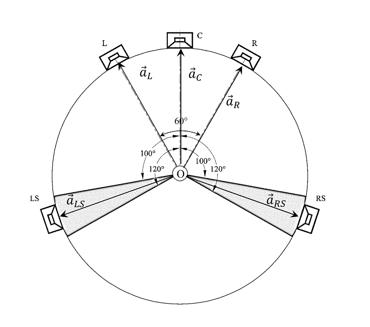
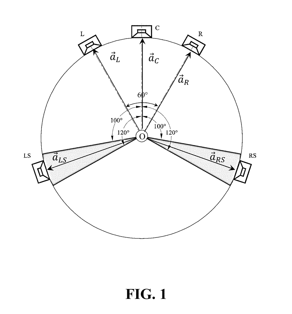
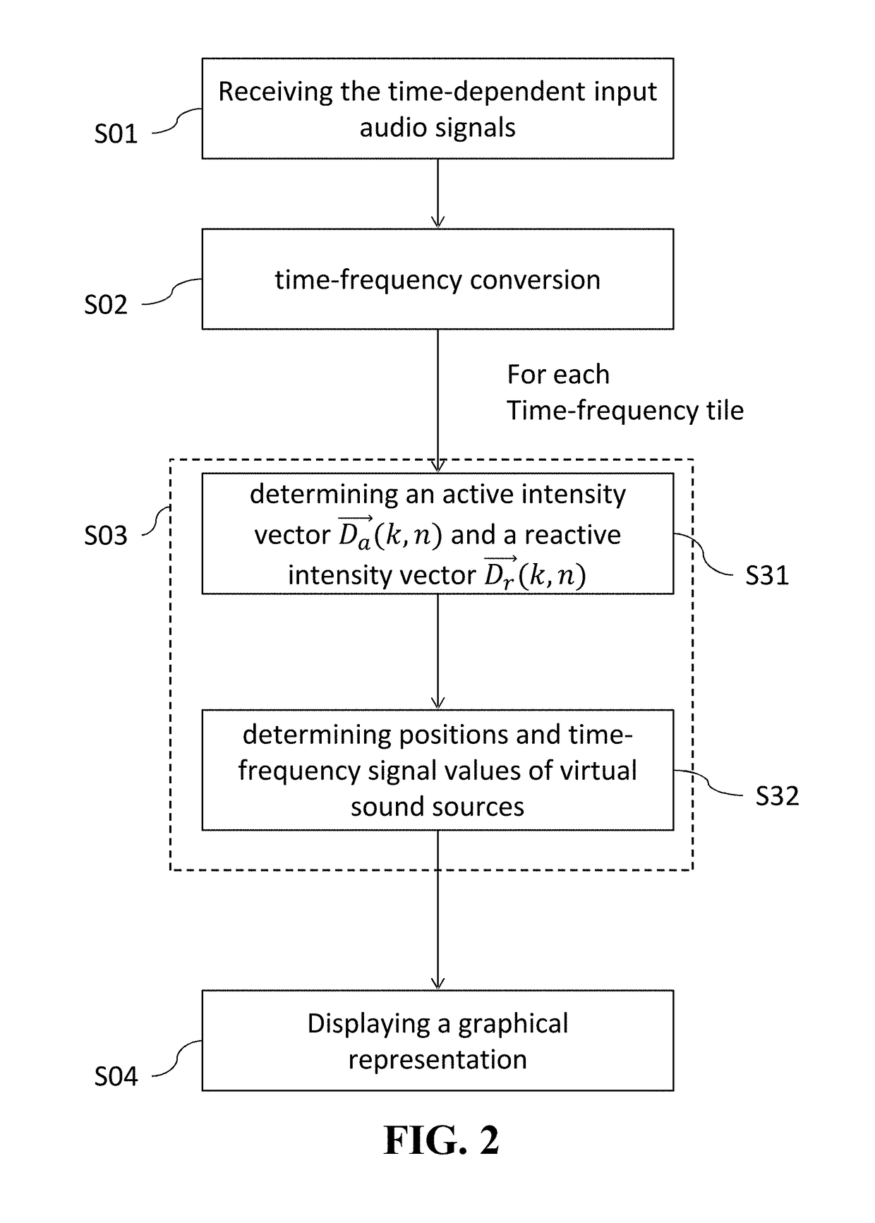
[0060]The operation of a directional sound activity analyzing unit, which may be part of a device comprising a processor, typically a computer, further provided with means for acquiring audio signals and means for displaying a visualization of sound activity data, for example visual display unit such as a screen or a computer monitor. The directional sound activity analyzing unit comprises means for executing the described method, such as a processor or any computing device, and a memory for buffering signals or storing various process parameters.

[0061]The directional sound activity analyzing unit receives an input signal constituted by a multichannel audio signal. This multichannel audio signal comprises K time-dependent input audio signals associated with K input audio channels, each time-dependent input audio signal being associated with an input channel. Each channel is associated with spatial information. Spatial information describes the location of the associated loudspeaker ...


PUM


Abstract

A method for visualizing a directional sound activity of a multichannel audio signal, wherein the multichannel audio signal comprises time-dependent input audio signals, comprising determining a directional sound activity vector from virtual sound sources determined from an active directional vector and a reactive directional vector determined from time-frequency representations of different input audio signals for each one of a plurality of time-frequency tiles; determining a contribution of each one of said directional sound activity vectors within sub-divisions of space on the basis of directivity information related to each sub-divisions of space and directional sound activity level within said sub-division of space by summing said contributions; displaying a visualization of the directional sound activity of the multichannel audio signal by a graphical representation of directional sound activity level within said sub-division of space.

Description

CROSS-REFERENCE TO RELATED APPLICATIONS[0001]This application claims priority under 35 U.S.C 119(a) to European Patent Application No. 16306190.6 filed on Sep. 19, 2016, all of which is hereby expressly incorporated by reference into the present application.BACKGROUND OF THE INVENTION[0002]The invention relates to a method and apparatus for visualizing the directional sound activity of a multichannel audio signal.[0003]Audio is an important medium for conveying any kind of information, especially sound direction information. Indeed, the human auditory system is more effective than the visual system for surveillance tasks. Thanks to the development of multichannel audio format, spatialization has become a common feature in all domains of audio: movies, video games, virtual reality, music, etc. For instance, when playing a First Person Shooting (FPS) game using a multichannel sound system (5.1 or 7.1 surround sound), it is possible to localize enemies thanks to their sounds.[0004]Typi...

Claims


Application Information

Patent Timeline
IPC IPC(8): H04S7/00H04R29/00H04S3/00G06F3/16
CPCH04S7/303H04R29/008H04S3/008G06F3/165H04S2400/15H04S2400/01H04S2400/11H04S3/02H04S7/30G10L19/008G10L19/02H04S7/40H04R5/02H04R5/04
Inventor GREFF, RAPHAEL NICOLASPHAM, HONG CONG TUYEN
Owner A VOLUTE
Learn More