Liquid discharge apparatus

a liquid discharge apparatus and liquid discharge technology, applied in the direction of printed circuit details, cross-talk/noise/interference reduction, printing, etc., can solve the problems of difficulty in keeping track of determining the state of the head modul

Active Publication Date: 2018-03-29
SEIKO EPSON CORP
View PDF0 Cites 2 Cited by
  • Summary
  • Abstract
  • Description
  • Claims
  • Application Information

AI Technical Summary

Benefits of technology

[0021]In this case, superimposition of the noise caused by driving the liquid discharge head on the state signal can be prevented.

Problems solved by technology

The noise-superimposed state signal makes it difficult to keep track of the state of the head module and to appropriately determine the state of the head module.

Method used


Image

  • Liquid discharge apparatus
  • Liquid discharge apparatus
  • Liquid discharge apparatus

Examples


embodiment

A. Embodiment

[0034]As an example liquid discharge apparatus, this embodiment uses an ink jet printer that forms an image on recording paper P, which is an example “recording medium”, by discharging ink, which is an example “liquid”.

1. Outline of Ink Jet Printer

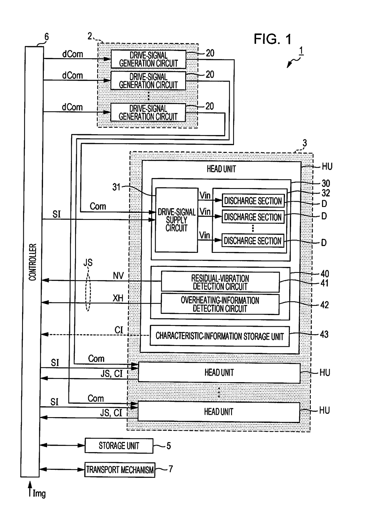
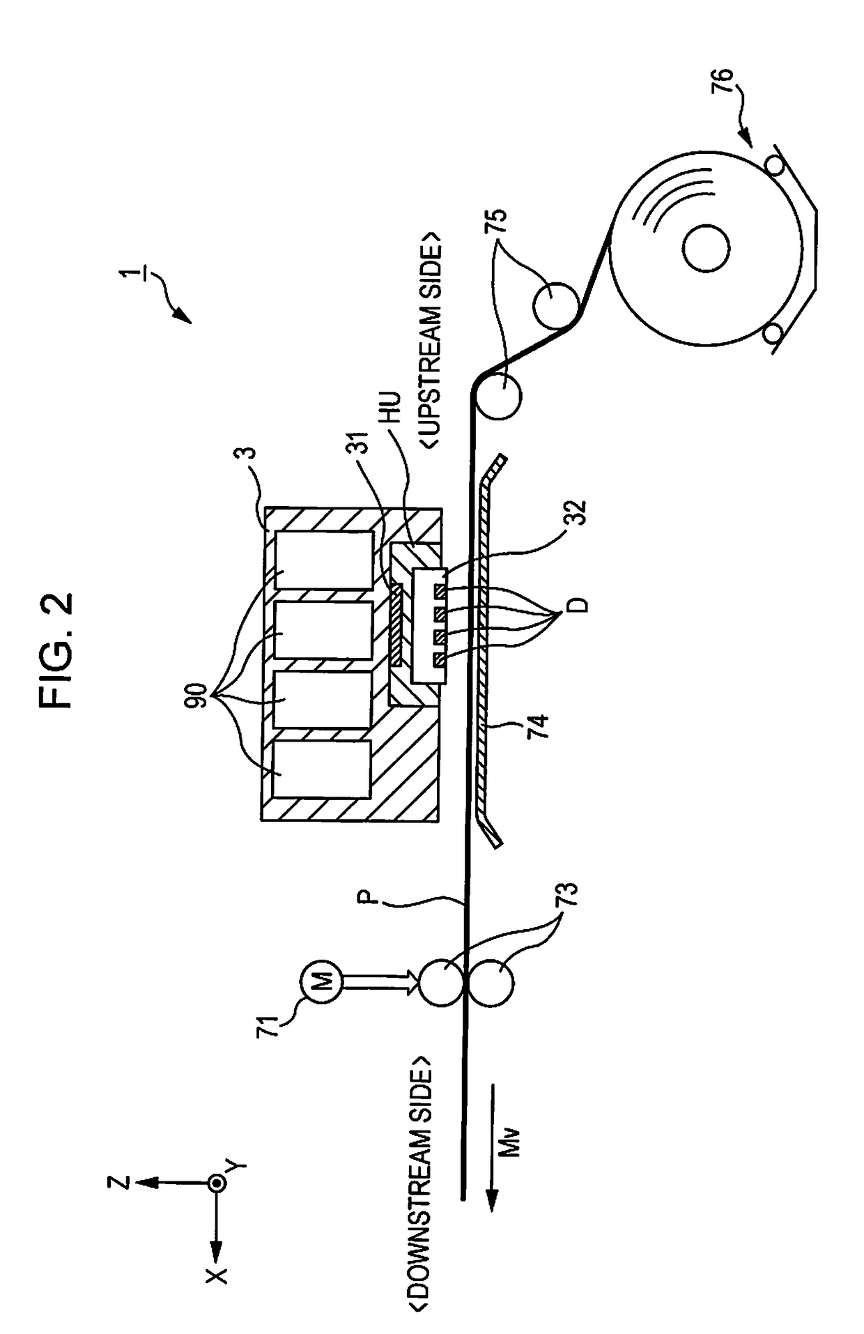
[0035]With reference to FIG. 1 and FIG. 2, an ink jet printer 1 according to the embodiment will be described. FIG. 1 is a functional block diagram of the ink jet printer 1 according to the embodiment. FIG. 2 is a partial sectional view schematically illustrating an inner structure of the ink jet printer 1.

[0036]Print data Img that represents an image to be formed by the ink jet printer 1 is supplied to the ink jet printer 1 from a host computer (not illustrated) such as a personal computer, a digital camera, or the like. The ink jet printer 1 performs print processing for forming on recording paper P the image represented by the print data Img, which is supplied from the host computer. Although details will be described below...

modification 1

[0084]In the above-described embodiment, the head unit HU includes the residual-vibration detection circuit 41 and the overheating-information detection circuit 42; however, the invention is not limited to this example, and the head unit HU may include at least one of the residual-vibration detection circuit 41 and the overheating-information detection circuit 42. In other words, in the above-described embodiment, the state signal JS includes the residual-vibration signal NV and the overheating-notification signal XH; however, the invention is not limited to this example, the state signal JS may include at least one of the residual-vibration signal NV and the overheating-notification signal XH.

[0085]In the above-described embodiment, the head unit HU includes the characteristic-information storage unit 43; however, the invention is not limited to this example, the head unit HU may omit the characteristic-information storage unit 43.

modification 2

[0086]In the above-described embodiment and modification, the range YP is 297 mm or greater and the liquid discharge head 3 is provided with the nozzles N that are arranged so as to extend within the range YNL of 297 mm or greater; however, the invention is not limited to this example, and the range YP may be less than 297 mm. In this case, the liquid discharge head 3 may be provided with the nozzles N such that the nozzles N extend in a range that covers the range YP.

[0087]In the above-described embodiment and the modification, the liquid discharge head 3 is provided with the nozzles N that are arranged such that printing can be performed at a dot density of 600 dpi or greater; however, the invention is not limited to this example, and the liquid discharge head 3 may be provided with the nozzles N that are arranged so as to enable printing only at a dot density less than 600 dpi.


PUM

PropertyMeasurementUnit
widthaaaaaaaaaa
temperatureaaaaaaaaaa
conductiveaaaaaaaaaa

Abstract

A liquid discharge apparatus includes a liquid discharge head including a head module provided with a discharge section configured to be driven by a drive signal and discharge a liquid and a supply section configured to supply the drive signal to the discharge section in accordance with a designation signal for designating an operation in the discharge section, and a state signal output section configured to output a state signal, and a wire section including a first wire to which the state signal is supplied, a second wire configured to supply the designation signal, and a third wire configured to supply the drive signal. The first wire includes a first shielding layer containing a conductive material, a second shielding layer containing a conductive material, and a first conductor provided between the first shielding layer and the second shielding layer, the first conductor being configured to transmit the state signal.

Description

[0001]This application claims priority to Japanese Patent Application No. 2016-191274 filed on Sep. 29, 2016. The entire disclosure of Japanese Patent Application No. 2016-191274 is hereby incorporated herein by reference.BACKGROUND1. Technical Field[0002]The present invention relates to a liquid discharge apparatus.2. Related Art[0003]Liquid discharge apparatuses such as an ink jet printer perform print processing by driving discharge sections in a liquid discharge head and discharging liquid such as ink contained in cavities of the discharge sections to form an image on a recording medium. Such a liquid discharge apparatus typically supplies a drive signal for driving discharge sections to a liquid discharge head via a wire such as a flexible flat cable (FFC) (see JP-A-2016-093973). Some liquid discharge apparatuses detect residual vibrations generated in a discharge section that has been driven by a drive signal, and based on the residual vibrations, determine whether the liquid ...

Claims


Application Information

Patent Timeline
Patent Type & Authority Applications(United States)
IPC IPC(8): B41J2/14B41J2/025B41J2/045
CPCB41J2/14209B41J2/025B41J2/04591B41J2/04581B41J2/14274B41J2/14153B41J2002/14217B41J2/01B41J2/04541B41J2/04563B41J2/04588B41J2/04593B41J2/14233B41J2002/14491Y10T29/49124H05K1/0218H05K1/0219H05K1/0298
Inventor MATSUMOTO, YUSUKEMATSUYAMA, TORU
Owner SEIKO EPSON CORP
Why Eureka
Try Eureka