Oil injection adapter and system

a technology of oil injection adapter and oil tank, which is applied in the direction of liquid dispensing, manual lubrication, discharging means, etc., can solve the problems of unregulated amount of fogging oil, unneeded wear and damage to the engine, so as to prevent engine contamination and prevent engine contamination.

Active Publication Date: 2018-03-29
MACCHIARELLA KIMBERLY DAWN
View PDF0 Cites 2 Cited by
  • Summary
  • Abstract
  • Description
  • Claims
  • Application Information

AI Technical Summary

Benefits of technology

[0027]In one form, the method further includes the steps of: providing a tool for receiving the first adapter and first container, placing the first adapter and first container into the tool prior to threading the first adapter into the first sparkplug hole; preventing contamination of the engine by withdrawing the first adapter and first container from the tool after the first adapter is threaded into the first sparkplug hole; and leaving the first adapter in the first sparkplug hole.
[0028]In one form, the method further includes the steps of: placing the second adapter and second container into the tool prior to threading the second adapter into the second sparkplug hole of the engine; preventing contamination of the engine by withdrawing the second adapter and second container from the tool after the second adapter is threaded into the second sparkplug hole; and leaving the second adapter in the second sparkplug hole.

Problems solved by technology

This apparatus and method however are not without their drawbacks.
Such contaminants then scour vital engine parts such as the cylinder walls and rings, causing unneeded wear and damage to the engine.
Additionally, the amount of fogging oil is not well regulated with the present application from a multi-use can.
Too little fogging oil results in an unprotected engine, exposing the cylinder walls and other internal components to corrosion over a prolonged storage.
An excess of fogging oil can lead to an oily mess on the exterior of the engine as the fogging oil bubbles out of the spark plug hole, and further poses a fire risk if not removed from the exterior of the engine.
Additionally, excess oil within the cylinder may cause fluid lock of the cylinder.
Further, there is a need to plug the spark plug hole of a cylinder when the spark plug is removed for other maintenance reasons.
The use of these items can introduce contaminants that might have collected on the items themselves.

Method used


Image

  • Oil injection adapter and system
  • Oil injection adapter and system
  • Oil injection adapter and system

Examples


Embodiment Construction

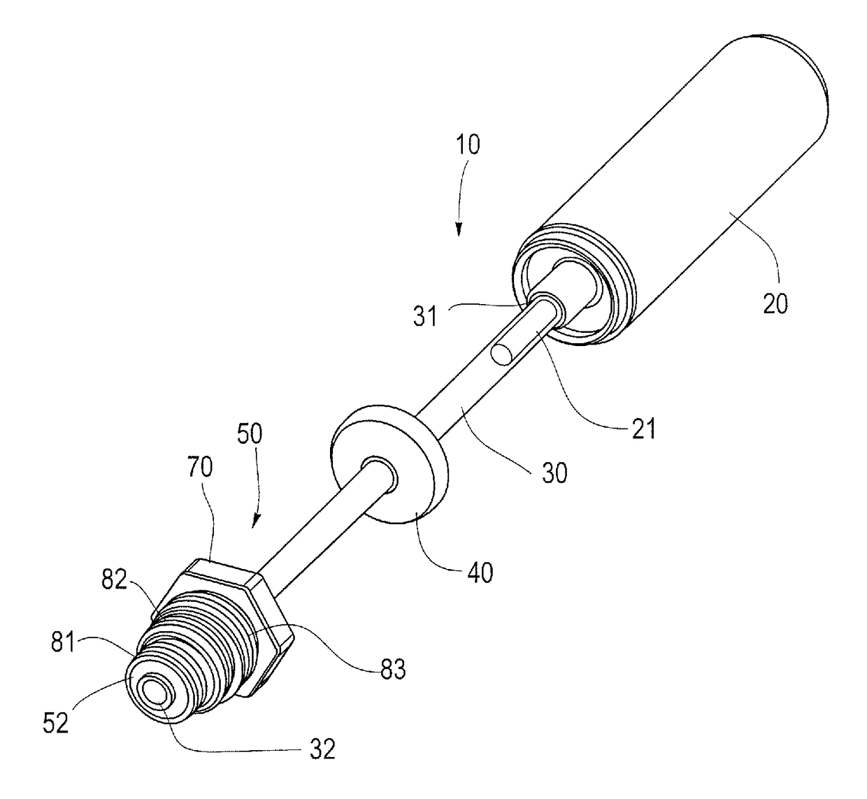
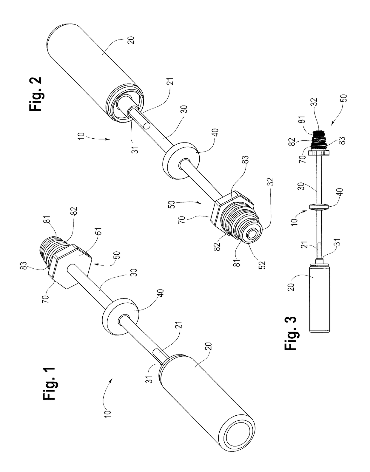
[0059]With reference to FIGS. 1, 2 and 3, the dispensing system 10 includes a fluid container 20 for containing and dispensing a fluid. In the preferred embodiment the fluid is fogging or storage oil intended for an internal combustion engine. The fluid container 20 is typically an aerosol can containing the fluid to be dispensed, along with a propellant, allowing the fluid to be expelled from a nozzle or other orifice on the can or fluid container 20. In the preferred embodiment shown in the figures, the fluid container 20 includes a valve 21 to selectively dispense or expel fluid from the fluid container 20.

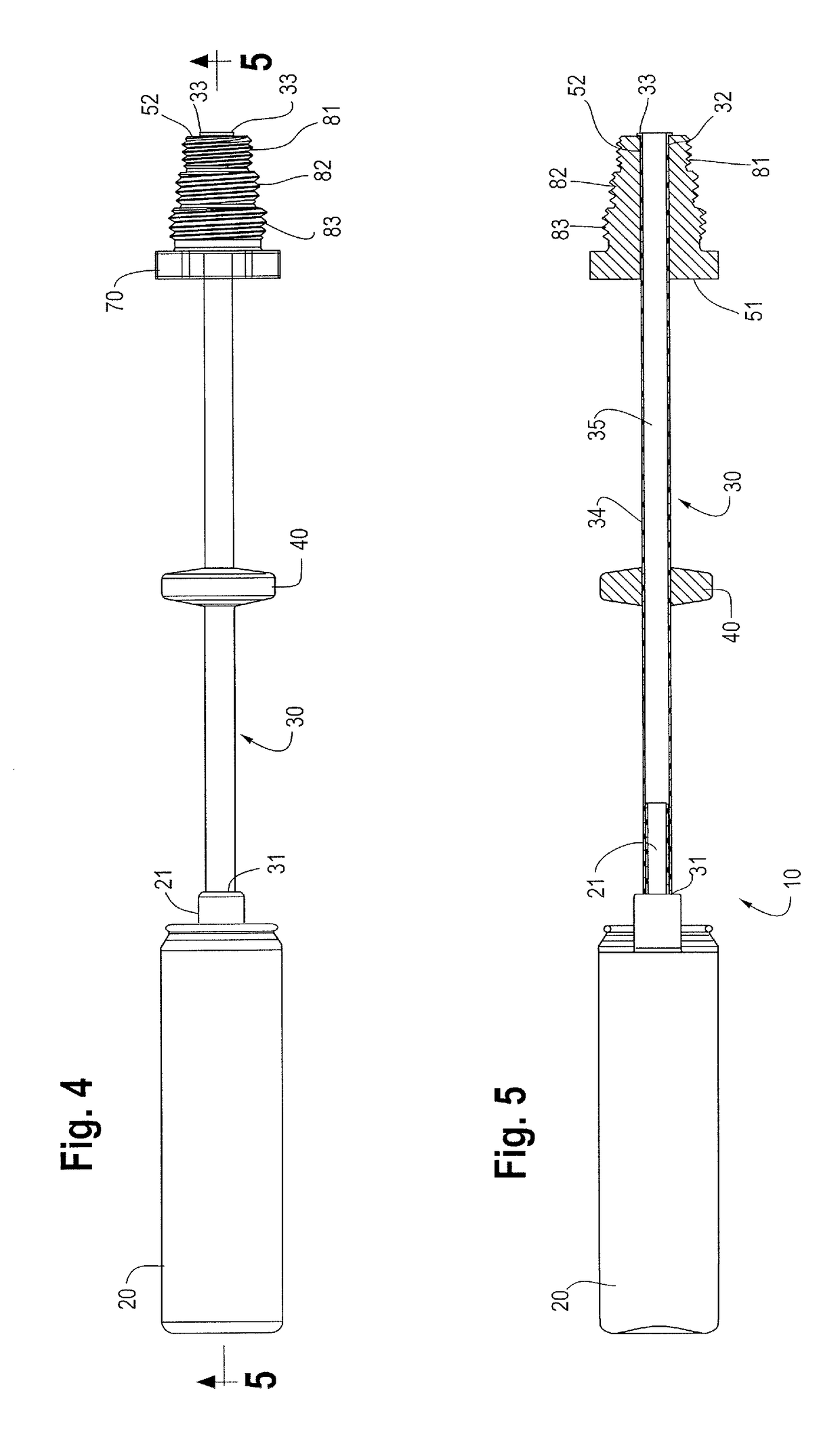
[0060]The fluid dispensing system 10 further includes a dispensing tube 30 having a first end 31 and a second end 32. The dispensing tube 30 includes a wall 34 defining an inner conduit 35. In operation, the dispensing tube 30 communicates fluid from its first end 31 to its second end 32 along or through the inner conduit 35. In the most preferred embodiment, the dispensing tub...


PUM


Abstract

The invention disclosed herein is a system for dispensing storage or fogging oil into the cylinders of internal combustion engines prior to putting the engines up for storage, during storage, or when removing the engine from storage. The system includes a dispensing adapter for closing off the spark plug hole of an engine cylinder, the dispensing adapter including threads of different sizes and diameters to accommodate common spark plug thread sizes. The dispensing adapter may also be used to temporarily plug a spark plug hole when a spark plug is removed from an engine.

Description

FIELD OF THE INVENTION[0001]Fluid dispensing systems. More particularly, lubricating fluid dispensing systems to dispense storage or fogging oil into the cylinders of internal combustion engines prior to putting the engines up for storage, during storage, or when removing the engine from storage. The invention also pertains to plugs for spark plug holes of internal combustion engines.BACKGROUND ART[0002]Presently, fogging or storage oil is provided to a user in an aerosol can of a size suitable for multiple uses, typically a can containing 12 to 18 ounces of fluid. The can includes a nozzle at the top of the can and a dispensing tube or straw for insertion into the engine cylinder which the user desires to apply the fogging oil. In order to access the cylinder, the user removes the spark plug, sets it aside, inserts the dispensing tube into the spark plug hole, and presses down on the nozzle to dispense fogging oil or other desired fluid into the cylinder. This apparatus and method ...

Claims


Application Information

Patent Timeline
Patent Type & Authority Applications(United States)
IPC IPC(8): B65D25/48B65D83/28F16N3/02
CPCB65D25/48B65D83/28F16N3/02F16N3/04B65D83/30
Inventor MACCHIARELLA, KIMBERLY DAWN
Owner MACCHIARELLA KIMBERLY DAWN
Why Eureka
Try Eureka