Heating device

Active Publication Date: 2018-03-29
NGK SPARK PLUG CO LTD
View PDF2 Cites 0 Cited by
  • Summary
  • Abstract
  • Description
  • Claims
  • Application Information

AI Technical Summary

Benefits of technology

The patent aims to improve the uniformity of temperature across the holding surface of a semiconductor manufacturing process by minimizing the diameter of the electrode terminals. However, this may lead to damage to the joint portion between the electrode terminal and the power receiving electrode due to stress generated. The technical effect of the patent is to improve the surface thermal uniformity while suppressing damage to the joint portion to achieve better overall performance of the heating device.

Problems solved by technology

Thus, if the electrode terminal having relatively large length swings, the stress (the moment) is generated in the joint portion and, thus, the stress may damage the joint portion.

Method used


Image

  • Heating device
  • Heating device
  • Heating device

Examples


first embodiment

A. First Embodiment

[0032]A-1. Configuration of Heating Device

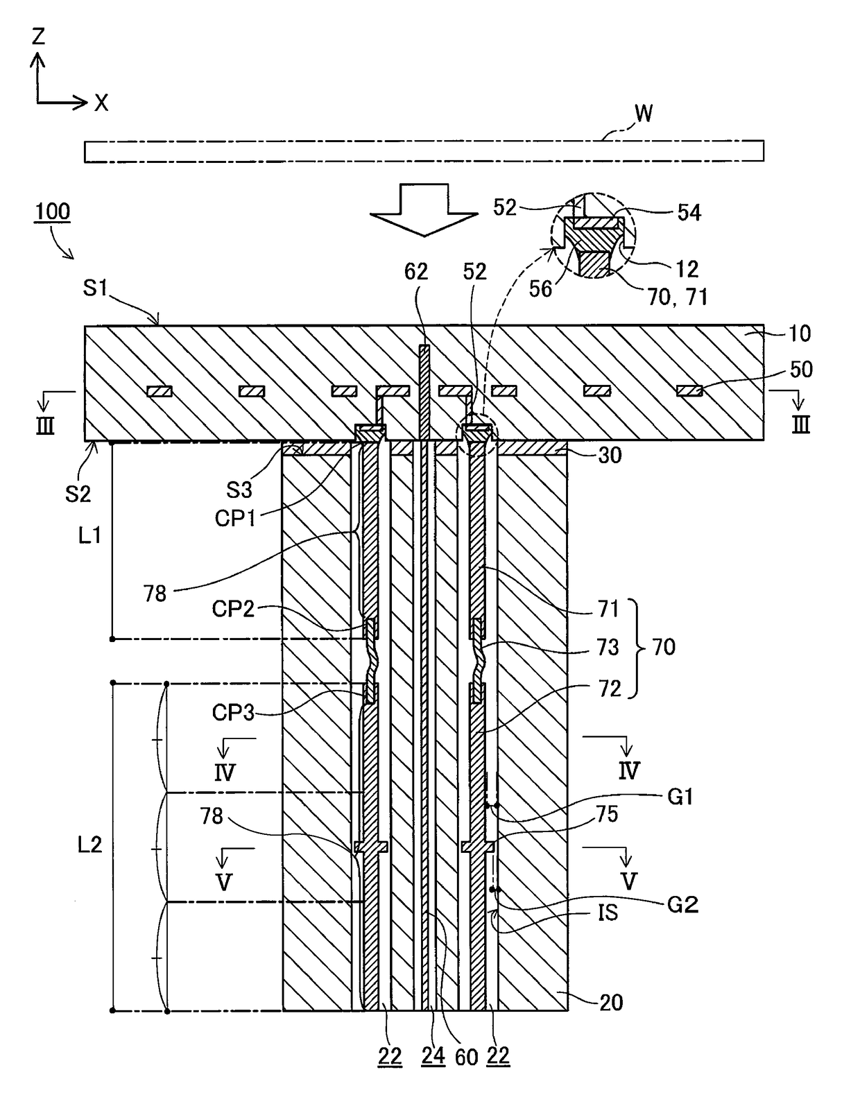
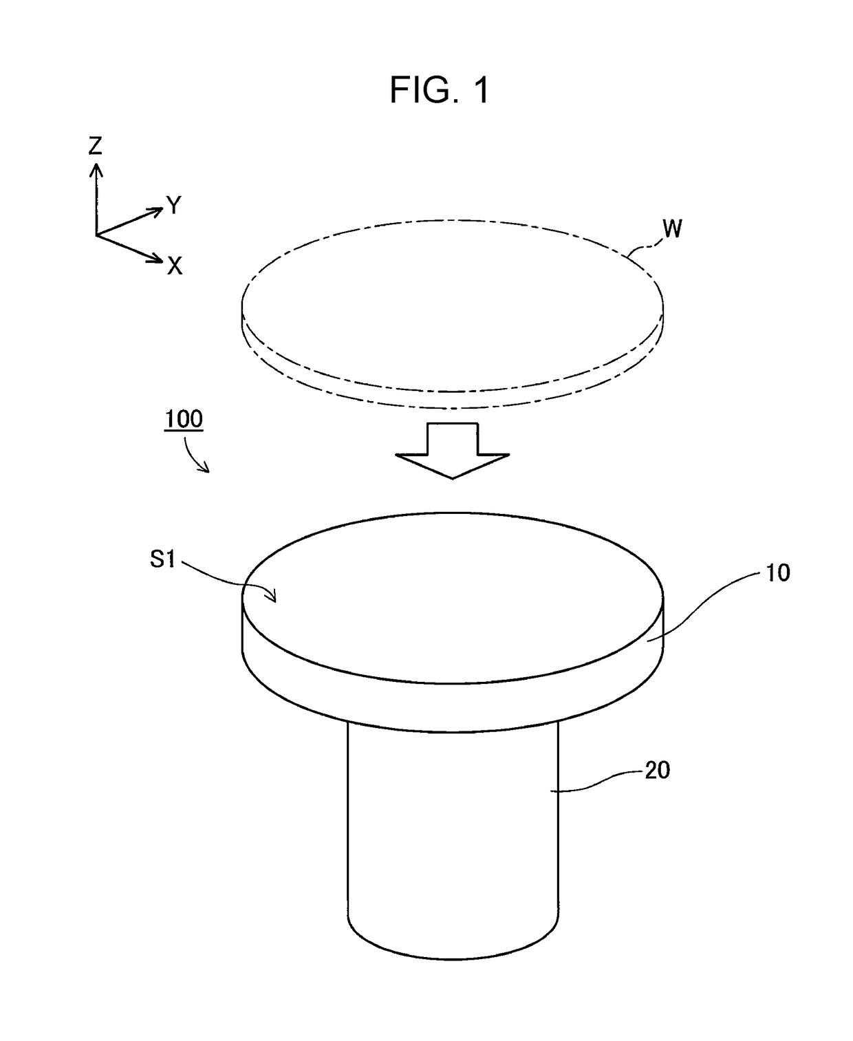
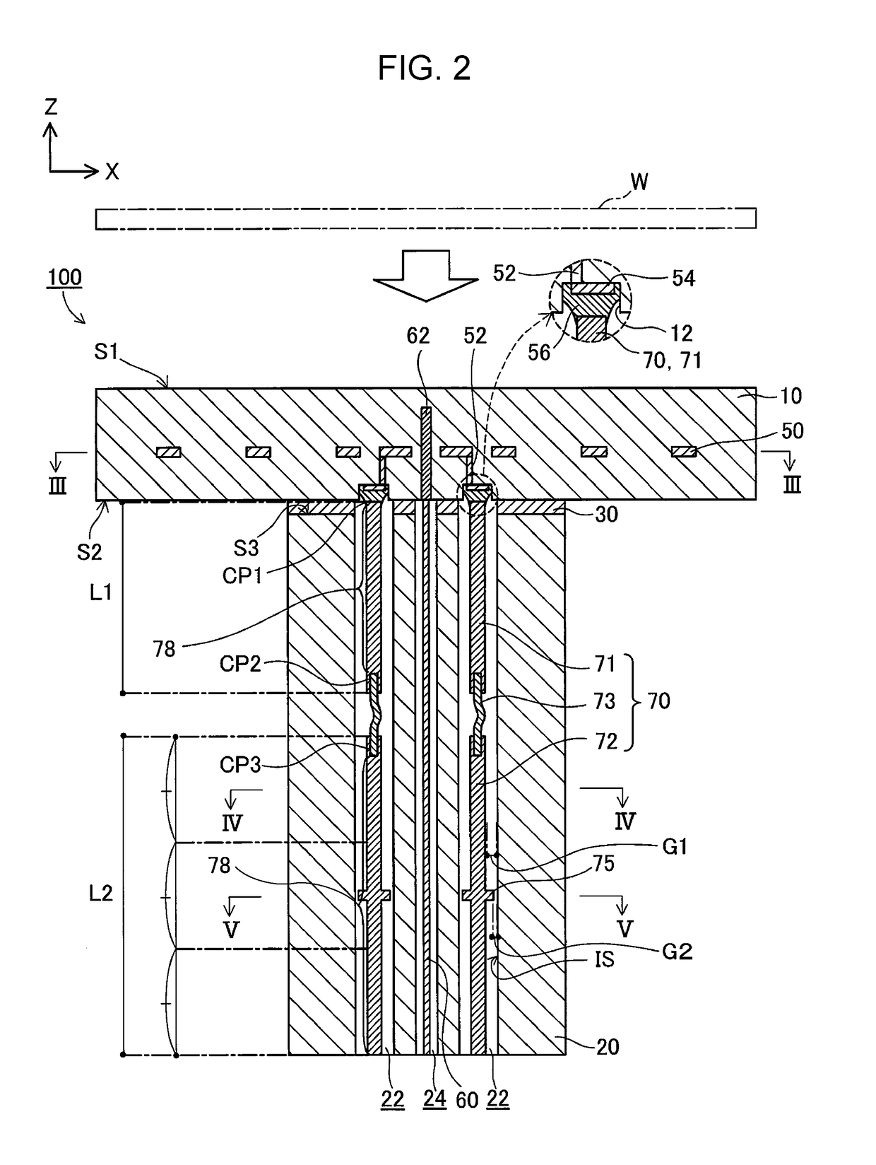
[0033]FIG. 1 is a perspective view schematically illustrating the external configuration of a heating device 100 according to a first embodiment. FIGS.FIGS. 2 to 5 are schematic illustrations of the cross-sectional configuration of the heating device 100 according to the first embodiment. FIG. 2 illustrates the XZ cross-sectional configuration of the heating device 100 taken along line II-II in FIGS.FIGS. 3 to 5. FIG. 3 illustrates the XY cross-sectional configuration of the heating device 100 taken along line III-III in FIG. 2. FIG. 4 illustrates the XY cross-sectional configuration of the heating device 100 taken along line IV-IV in FIG. 2. FIG. 5 illustrates the XY cross-sectional configuration of the heating device 100 taken along line V-V in FIG. 2. Note that an enlarged view of a portion around a power receiving electrode 54 (described below) is included in FIG. 2. In each of FIGS. 1 to 5, the X, Y, and Z axes which ...

second embodiment

B. Second Embodiment

[0076]FIGS. 9 and 10 are schematic illustrations of the cross-sectional configuration of a heating device 100a according to the second embodiment. FIG. 9 illustrates the XZ cross-sectional configuration of the heating device 100a taken along line IX-IX in FIG. 10 (the same position as in FIG. 2), and FIG. 10 illustrates the XY cross-sectional configuration of the heating device 100a taken along line X-X in FIG. 9 (the same position as in FIG. 5). Hereinafter, the constituent elements of the heating device 100a according to the second embodiment that are identical to the constituent elements of the heating device 100 according to the above-described first embodiment are denoted by the same reference numerals, and the description of the constituent elements is not repeated as appropriate.

[0077]As illustrated in FIGS. 9 and 10, the configuration of a columnar support member 20a of the heating device 100a according to the second embodiment differs from the configurat...

third embodiment

C. Third Embodiment

[0083]FIGS. 11 and 12 are schematic illustrations of the cross-sectional configuration of a heating device 100b according to a third embodiment. FIG. 11 illustrates the XZ cross-sectional configuration of the heating device 100b taken along line XI-XI in FIG. 12 (the same position as in FIG. 2), and FIG. 12 illustrates an XY cross-sectional configuration of the heating device 100b taken along line XII-XII in FIG. 11 (at the same position in FIG. 5). Hereinafter, the constituent elements of the heating device 100b according to the third embodiment that are identical to the constituent elements of the heating device 100 according to the above-described first embodiment are denoted by the same reference numerals, and the description of the constituent elements is not repeated as appropriate.

[0084]Hereinafter, in each of the electrode terminal units 70, a structure including a portion of the first columnar member 71 other than the joint portion CP1 between the first c...


PUM

PropertyMeasurementUnit
Diameteraaaaaaaaaa
Diameteraaaaaaaaaa
Lengthaaaaaaaaaa

Abstract

A heating device includes a holding member having a resistive heating element, a columnar support member joined to the holding member, power receiving electrodes connected to the resistive heating element, and an electrode terminal unit disposed in each of through holes in the columnar support member. Each of the electrode terminal units includes a first columnar member having one end portion connected to the power receiving electrode and the other end portion connected to a metal stranded wire, and a second columnar member having an end portion connected to the metal stranded wire. A columnar member assembly having a portion of the first columnar member and a portion of the second columnar member includes a general portion and a large-diameter portion. The distance between the large-diameter portion and an inner peripheral surface of the through hole is smaller than the distance between the general portion and the inner peripheral surface.

Description

CROSS REFERENCE TO RELATED APPLICATION[0001]The present application claims priority to Japanese Patent No. 2016-185094, which was filed on Sep. 23, 2016, the disclosure of which is herein incorporated by reference in its entirety.BACKGROUND OF THE INVENTIONField of the Invention[0002]The technology disclosed herein relates to a heating device.Description of Related Art[0003]Heating devices (also referred to as “susceptors”) for heating an object (for example, a semiconductor wafer), while holding the object, to a predetermined treatment temperature (for example, about 400 to 650° C.) have been developed. The heating device is used, for example, as a part of a semiconductor manufacturing apparatus such as a film deposition apparatus (for example, a CVD apparatus or a sputtering apparatus) and etching equipment (for example, plasma etching equipment).[0004]In general, a heating device includes a plate-like holding member having a holding surface and a back surface which are substantia...

Claims


Application Information

Patent Timeline
IPC IPC(8): C23C16/458C23C16/509C23C16/52H01J37/32H01L21/67
CPCC23C16/4586C23C16/5096C23C16/52H01J37/32532H01L21/67103H05B3/02H05B3/03H05B3/08H05B2203/017C23C14/541H01J37/32724H01L21/68792
Inventor KURANO, JUNTANAKA, KAZUTAKA
Owner NGK SPARK PLUG CO LTD
Why Eureka
Try Eureka