Heat pipe structure

a technology of heat pipe and heat pipe structure, which is applied in the direction of lighting and heating apparatus, electrical equipment, cooling/ventilation/heating modifications, etc., can solve the problems of large heat generation of high-performance electronic devices, limited internal space for accommodating other components, and small electronic devices. , to achieve the effect of increasing the configuration flexibility reducing the thickness of the heat pipe structur

Active Publication Date: 2018-03-29
DELTA ELECTRONICS INC
View PDF13 Cites 13 Cited by
  • Summary
  • Abstract
  • Description
  • Claims
  • Application Information

AI Technical Summary

Benefits of technology

[0025]As mentioned above, the heat pipe structure of this disclosure is manufactured by connecting the first and second plates, and this configuration can reduce the thickness of the heat pipe structure. The side wall and contour of the chamber can be properly designed and changed based on the configuration of the chamber instead of the conventional rectangular. Moreover, the chamber further has at least one coupling portion and at least three extending portions, so that the heat pipe structure can penetrate between the internal components of the electronic device. This configuration can adapt to the limited space inside the electronic device, increase the configuration flexibility of the heat pipe structure, and properly utilize the internal space of the electronic device.

Problems solved by technology

Since the entire size of the electronic device becomes smaller, the internal space for accommodating the other components is limited.
However, the high performance electronic device will generate a lot of heat in operation.
If the heat cannot be dissipated immediately, the temperature inside the electronic device will increase, which may damage the internal components and decrease the function and lifetime of the electronic device.
However, the thickness and configuration of the heat pipe structure are limited to the arrangement of the components inside the electronic device.

Method used


Image

  • Heat pipe structure
  • Heat pipe structure
  • Heat pipe structure

Examples


Embodiment Construction

[0035]The present invention will be apparent from the following detailed description, which proceeds with reference to the accompanying drawings, wherein the same references relate to the same elements.

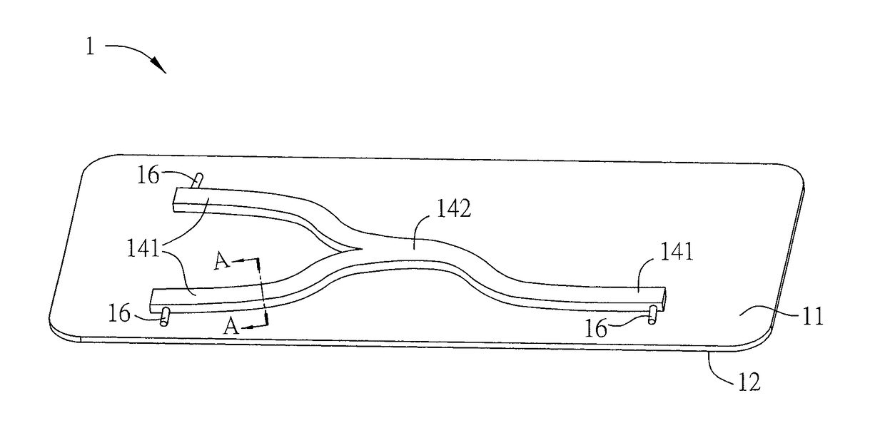
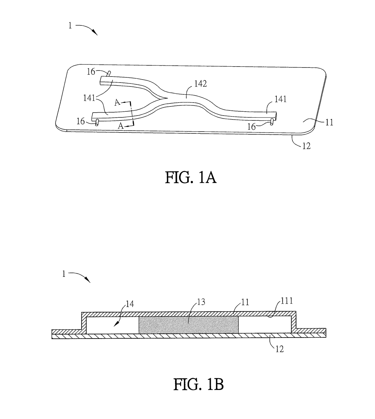
[0036]The basic structure and the feature of an embodiment of the heat pipe structure of this disclosure will be described hereinafter with reference to FIGS. 1A and 1B. FIG. 1A is a schematic diagram of a heat pipe structure according to an embodiment of the disclosure, and FIG. 1B is a sectional view of a part of the heat pipe structure of FIG. 1A along the line A-A.

[0037]A heat pipe structure 1 includes a first plate 11, a second plate 12, and a plurality of wick structures 13. The second plate 12 is connected to the first plate 11 to faun a chamber 14. The wick structures 13 are disposed in the chamber 14. A distribution shape of the wick structures 13 is approximately the same as a shape of a portion of the chamber 14. The chamber 14 is formed by at least one coupling portion 142...


PUM


Abstract

A heat pipe structure includes a first plate, a second plate and a plurality of wick structures. The second plate is connected to the first plate to form a chamber. The wick structures are disposed in the chamber, and the distribution shape of the wick structures is approximately the same as the shape of a portion of the chamber. The chamber is formed by at least one coupling portion and three or more extending portions. The coupling portion communicates with the extending portions, and the contour of the connected first and second plates is different from that of the chamber.

Description

CROSS REFERENCE TO RELATED APPLICATIONS[0001]The non-provisional patent application claims priority to U.S. provisional patent application with Ser. No. 62 / 401,397 filed on Sep. 29, 2016. This and all other extrinsic materials discussed herein are incorporated by reference in their entirety.[0002]This Non-provisional application claims priority under 35 U.S.C. § 119(a) on Patent Application No(s). 201710813463.3 filed in People's Republic of China on Sep. 11, 2017, the entire contents of which are hereby incorporated by reference.BACKGROUND OF THE INVENTIONField of Invention[0003]The present disclosure relates to a heat pipe structure having at least three extending portions.Related Art[0004]The existing electronic devices are developed to be portable, have a compact size and light weight, and provide with more additional functions. Since the entire size of the electronic device becomes smaller, the internal space for accommodating the other components is limited. However, the high ...

Claims


Application Information

Patent Timeline
Patent Type & Authority Applications(United States)
IPC IPC(8): F28D15/04F28F9/26H05K7/20
CPCF28D15/04F28F9/26H05K7/20336F28F2275/067F28F2275/061F28F2275/065F28F2275/025F28F2210/02F28F3/12F28D15/0233F28D15/0283
Inventor HUANG, SHIH-LIN
Owner DELTA ELECTRONICS INC
Why Eureka
Try Eureka