
Liquid lens array based on electrowetting method and method of manufacturing the same, and display device using the same

a technology of liquid lens array and electrowetting, which is applied in the field of liquid lens array, can solve the problems of reduced resolution, increased volume of display panel, and difficulty in forming high-quality 3d images, and achieves the effect of higher quality

Inactive Publication Date: 2018-03-29
KOREA ADVANCED INST OF SCI & TECH
View PDF7 Cites 3 Cited by
  • Summary
  • Abstract
  • Description
  • Claims
  • Application Information

AI Technical Summary

Benefits of technology

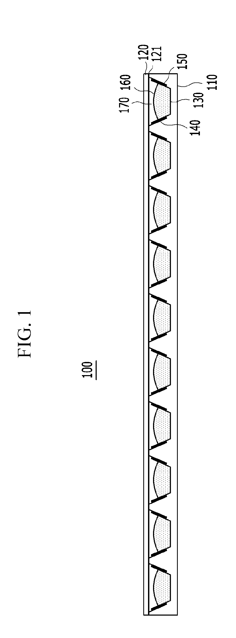
The present invention is a liquid lens array that uses electrowetting to create high-quality 3D images with improved resolution and more viewpoints. The invention allows for two or more viewpoints without loss of resolution, providing a more varied and natural view for the observer. Overall, the invention results in a better 3D image than traditional methods. The patent also describes a method of manufacturing the liquid lens array and a display device that uses it.

Problems solved by technology

On the other hand, the resolution is decreased as much as the multi-view, so that it is difficult to form a high quality 3D image.
In order to solve the chronic problem, a method of attaching several beam projectors to a rear surface of a display panel and the like are used, but the method has a problem in that a volume of the display panel is increased and power consumption is increased.

Method used

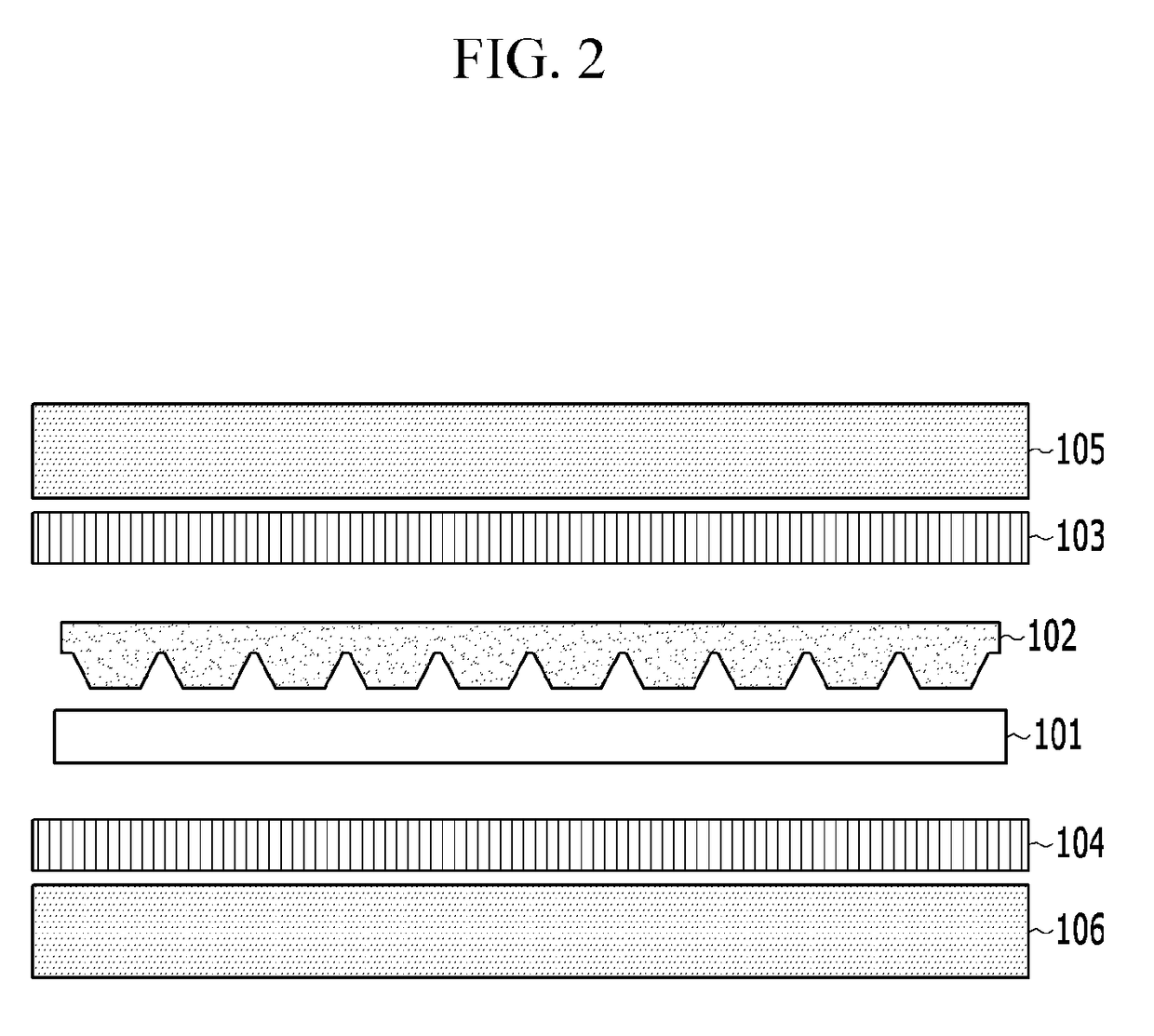

Image

  • Liquid lens array based on electrowetting method and method of manufacturing the same, and display device using the same
  • Liquid lens array based on electrowetting method and method of manufacturing the same, and display device using the same
  • Liquid lens array based on electrowetting method and method of manufacturing the same, and display device using the same

Examples


Embodiment Construction

[0033]In the following detailed description, only certain example embodiments of the present invention have been shown and described, simply by way of illustration. As those skilled in the art would realize, the described embodiments may be modified in various different ways, all without departing from the spirit or scope of the present invention. Accordingly, the drawings and description are to be regarded as illustrative in nature and not restrictive. Like reference numerals designate like elements throughout the specification.

[0034]Throughout the specification, unless explicitly described to the contrary, the word “comprise” and variations such as “comprises” or “comprising”, will be understood to imply the inclusion of stated elements but not the exclusion of any other elements. In addition, the terms “-er”, “-or” and “module” described in the specification mean units for processing at least one function and operation and can be implemented by hardware components or software com...


PUM

PropertyMeasurementUnit
Electric potential / voltageaaaaaaaaaa
Hydrophobicityaaaaaaaaaa

Abstract

Disclosed are a liquid lens array based on an electrowetting method, a method of manufacturing the same, and a display device using the same.The display device includes a display panel configured to display an image. A liquid lens array of the display device is disposed at a side of the display panel, on which an image is displayed, and is capable of controlling an optical axis of a lens, which is formed by a shape between a first liquid and a second liquid, which is not mixed with the first liquid, filled therein be inclined to left and right sides by using an electrowetting phenomenon. A controller controls the optical axis of the lens formed by the shape between the first liquid and the second liquid to be inclined to left and right sides by applying a voltage to the liquid lens array. The optical axis of the lens of the liquid lens array is controlled to be inclined to the left and right sides by the controller, so that it is possible to maintain resolution and increase the number of viewpoints, thereby implementing a high quality 3D image.

Description

CROSS-REFERENCE TO RELATED APPLICATION[0001]This application claims priority to and the benefit of Korean Patent Application No. 10-2016-0122203 filed in the Korean Intellectual Property Office on Sep. 23, 2016, the entire contents of which are incorporated herein by reference.BACKGROUND OF THE INVENTION(a) Field of the Invention[0002]The present invention relates to a liquid lens array based on an electrowetting method, a method of manufacturing the same, and a display device using the same.(b) Description of the Related Art[0003]Autostereoscopic 3D image technology has a form, in which a function of the stereoscopic glasses is mounted in a display, and a multi-view method is one of the methods for creating a 3D image. The multi-view method is divided into a parallax barrier method and a lenticular method again.[0004]In the case of the parallax barrier method, when a 3D image is reproduced, a barrier blocks most of the light, so that general brightness is considerably decreased, bu...

Claims


Application Information

Patent Timeline
IPC IPC(8): G02B27/22G02B3/12G02B3/00G02B26/00B29D11/00G02B30/28
CPCG02B27/2214G02B3/12G02B3/0031B29L2031/3475B29D11/00298B29K2033/12G02B26/005B29D11/00807G02B30/28G02B3/0037G02B30/27
Inventor WON, YONG HYUBKIM, JUNOHKIM, CHEOL JOONGSHIN, DOO-SEUBLEE, JUN SIK
Owner KOREA ADVANCED INST OF SCI & TECH
Learn More