
Solar cell and solar cell panel including the same

a solar cell and solar cell technology, applied in the field of solar cell and solar cell panel, can solve the problems of deteriorating lead adhesion properties, affecting and requiring long-term so as to improve the output and reliability of solar cell panel

Active Publication Date: 2018-03-29
SHANGRAO JINKO SOLAR TECH DEV CO LTD
View PDF3 Cites 2 Cited by
  • Summary
  • Abstract
  • Description
  • Claims
  • Application Information

AI Technical Summary

Benefits of technology

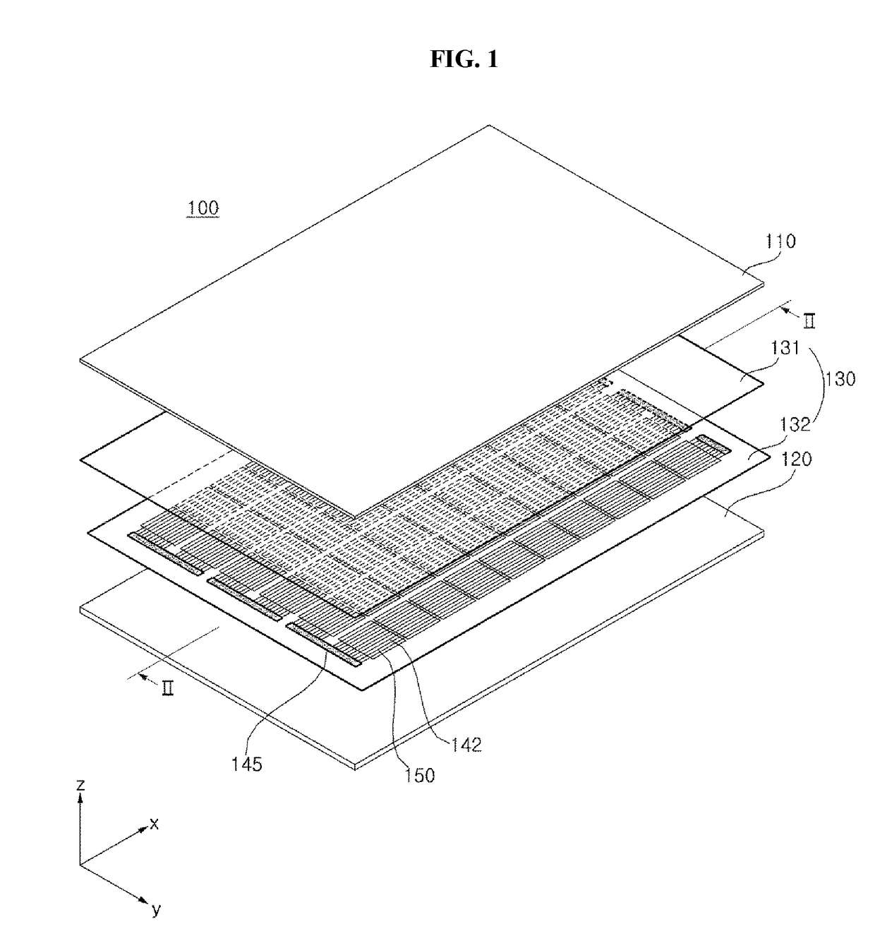
The invention provides a solar cell and panel that can increase output and reliability. This is achieved by using a bus bar with a small width and leads that have a wire shape to minimize light loss and movement of carriers. Adhesion properties are improved using plural regions with different arrangements and areas of pad portions, and a wide portion with a wide width at a portion adjacent to the outer pad. Additionally, by differentiating positions of outer pads and using a large number of leads with small width, cracks due to thermal stress can be prevented and reliability of the panel can be improved.

Problems solved by technology

A solar cell panel requires long-term reliability because the solar cell panel generates electricity for a long time in various environments.
However, an adhesion property of the lead may be deteriorated in a specific region.
If the adhesion property of the lead in the specific region is deteriorated, an output and a reliability of a solar cell panel may be deteriorated.

Method used


Image

  • Solar cell and solar cell panel including the same
  • Solar cell and solar cell panel including the same
  • Solar cell and solar cell panel including the same

Examples


embodiment 1

[0213]A plurality of solar cells having an electrode structure as shown in FIG. 15 were manufactured. In this instance, a semiconductor substrate included a single crystal silicon substrate having an n-type as a base region, a first conductive region formed of a doped region having a p-type, and a second conductive region formed of a doped region having an n-type. In this instance, a line portion of a bus bar included a main line portion and wide portions, each extending from an outer pad and connected to the main line portion via two inner pads. These solar cells were electrically connected using leads and thus a solar panel was manufactured.

embodiment 2

[0214]A solar cell panel was manufactured similarly to Embodiment 1 except that a line portion of a bus bar included a main line portion and wide portions, each extending from an outer pad and connected to the main line portion via one inner pad.

[0215]Based on Embodiments 1 and 2, a power drop rate was measured after a thermal cycling (TC) test was performed to the solar cell panels according to each of Embodiment 1 and Embodiment 2, and the results are shown in FIG. 29. Referring to FIG. 29, it can be seen that the power drop rates of the solar cell panels according to Embodiments 1 and 2 do not significantly decrease even when the thermal cycling tests were performed a large number of times, and the solar cell panels according to Embodiments 1 and 2 have excellent power drop ratios within 5%. Particularly, it can be seen that the power drop ratio of Embodiment 1 where a length of the line portion is relatively long is smaller than the power drop ratio of Embodiment 2.

[0216]Thus, i...


PUM


Abstract

Disclosed is a solar cell including a semiconductor substrate, a conductive region on or at the semiconductor substrate, and an electrode electrically connected to the conductive region. The electrode includes a plurality of finger lines formed in a first direction and parallel to each other and a bus bar electrically connected to the plurality of finger lines and formed in a second direction crossing the first direction. The bus bar includes a plurality of pad portions positioned in the second direction, and the bus bar has a plurality of regions, which are different from each other in at least one of an arrangement and an area of the plurality of pad portions, in the second direction.

Description

CROSS-REFERENCE TO RELATED APPLICATIONS[0001]This application claims the priority benefit of Korean Patent Application No. 10-2016-0124236 filed on Sep. 27, 2016, No. 10-2016-0126000 filed on Sep. 30, 2016, and No. 10-2016-0128103 filed on Oct. 5, 2016, in the Korean Intellectual Property Office, the disclosures of all of these applications are incorporated herein by reference in their entirety.BACKGROUND OF THE INVENTIONField of the Invention[0002]Embodiments of the invention relate to a solar cell and a solar cell panel including the same, and, more particularly, to a solar cell having an improved electrode structure and a solar cell panel including the same.Description of the Related Art[0003]Recently, as existing energy resources such as petroleum and coal are expected to be depleted, interest in alternative energy to replace them is increasing. Among them, a solar cell that converts solar energy into electric energy is attracting attention as a next-generation battery.[0004]A p...

Claims


Application Information

Patent Timeline
IPC IPC(8): H01L31/05H01L31/0224H01L31/0465H01L31/18
CPCH01L31/05H01L31/022425H01L31/0465H01L31/1868H01L31/0201H01L31/022433H01L31/0504H01L31/0508Y02E10/50
Inventor CHO, YUNHUISONG, WONDOOKIM, YOUNGJUNLEE, SUCHUNCHANG, SUNGHO
Owner SHANGRAO JINKO SOLAR TECH DEV CO LTD
Learn More