Thermoelectric Generator and Method for Producing a Thermoelectric Generator

Inactive Publication Date: 2018-03-29
ROBERT BOSCH GMBH
View PDF5 Cites 1 Cited by
  • Summary
  • Abstract
  • Description
  • Claims
  • Application Information

AI Technical Summary

Benefits of technology

[0042]The approach presented here makes it possible to achieve a reduction in the mechanical loading caused, inter alia, by thermomechanical stress, on the thermoelectric leads 104, 105 of the TEG 100 during the packaging and production process.
[0043]Furthermore, it is possible to achieve a reduction in the mechanical influences on the TEG 100 that are caused by stresses during production. For example, these loads occur when the sensor modules, fitted with the TEG 100, are being singled out of a larger panel by sawing. Mech

Problems solved by technology

As a result of the series connection of the many leads, the TEG may lose its functionality completely as a result of one connection being damaged.
The maximum stab

Method used


Image

  • Thermoelectric Generator and Method for Producing a Thermoelectric Generator
  • Thermoelectric Generator and Method for Producing a Thermoelectric Generator
  • Thermoelectric Generator and Method for Producing a Thermoelectric Generator

Examples


Example

[0030]In the following description of favorable exemplary embodiments of the present invention, elements, represented in the various figures, that are similar in their effect are denoted by the same or similar references, and description of these elements is not repeated.

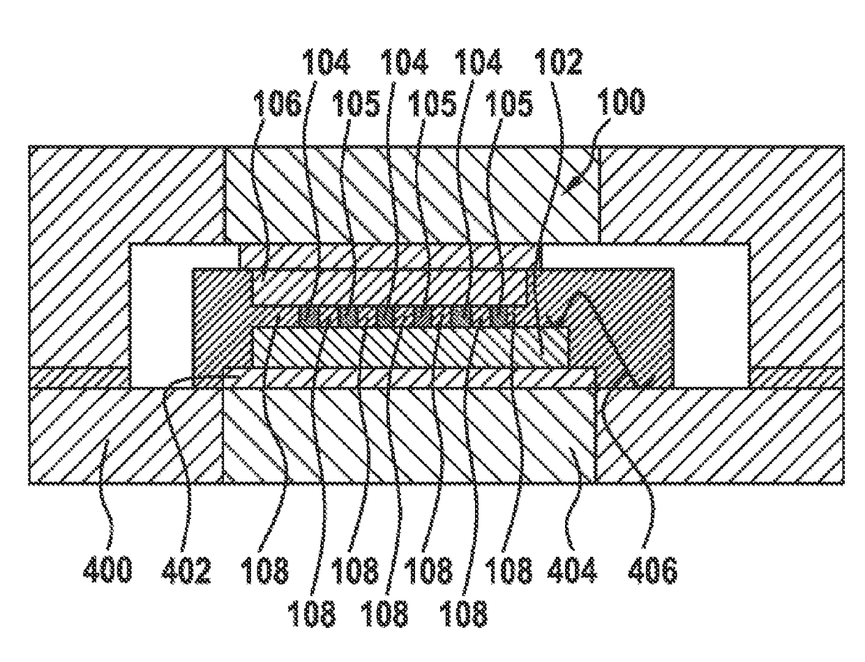
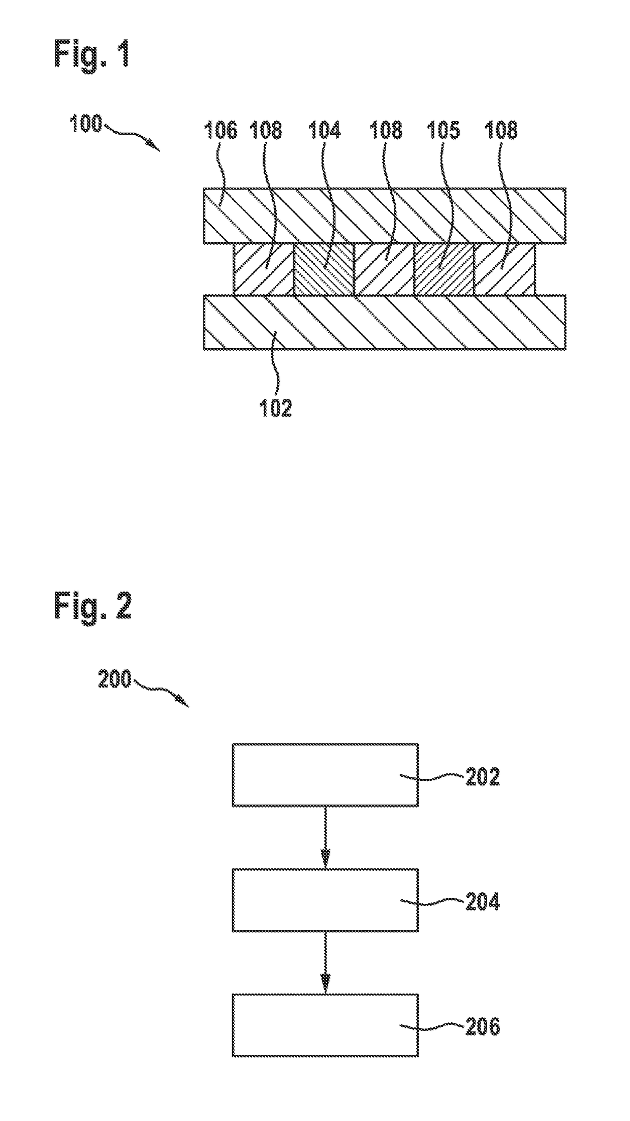
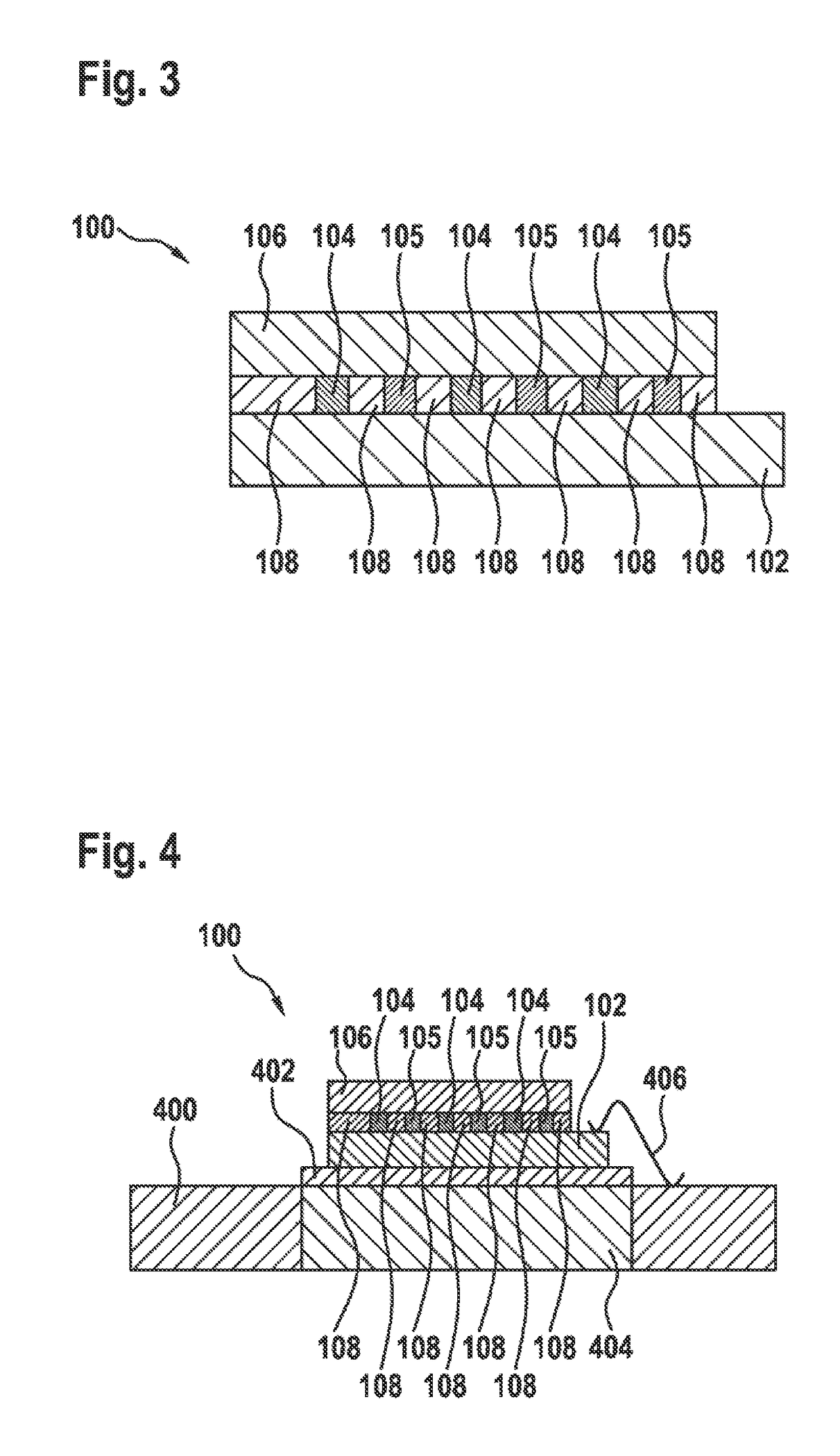
[0031]FIG. 1 shows a block diagram of a thermoelectric generator 100 according to an exemplary embodiment of the present invention. The thermoelectric generator 100 has a first substrate 102, a thermoelectric generator material 104 and 105 (n-doped and p-doped) and a second substrate 106. A first side of the generator materials 104 and 105 is connected in a thermally conductive manner to the first substrate 102. A second side of the generator materials 104 and 105 that is opposite the first side is connected in a thermally conductive manner to the second substrate 106. There is a support material 108 disposed between the first substrate 102 and the second substrate 106. The support material 108 mechanically connects...


PUM


Abstract

A method for producing a thermoelectric generator includes a preparation step, a connection step and an insertion step. In the preparation step, a first substrate, a thermoelectric generator material and a second substrate are prepared. In the connection step, the generator material is connected to the first substrate and the second substrate. In this way, a first side of the generator material is connected to the first substrate in a thermally and electrically conductive manner. A second side of the generator material, opposite the first side, is connected to the second substrate in a thermally and electrically conductive manner. In the insertion step, a support material is inserted between the first substrate and the second substrate, in order to support the first substrate and the second substrate against each other and/or to mechanically connect them together.

Description

Prior art[0001]The present invention relates to a method for producing a thermoelectric generator, and to a corresponding thermoelectric generator.[0002]The “Internet of Things” (IoT) is identified as one of the most important future developments in information technology. The IoT is understood to mean that, not only people have access to the Internet and are networked via the latter, but that devices are also networked to each other via the Internet. One area of the “Internet of Things” has its base in the area of production automation and home automation. For example, temperature sensors on the heating system, gyroscopes, acceleration sensors, pressure sensors and microphones may be used for this.[0003]The electrical energy required for this can be obtained from the environment by means of so-called “energy harvesters”. The classic harvesters are PV cells for obtaining energy from sunlight, and the thermoelectric generators (TEG), described here, for obtaining energy from a temper...

Claims


Application Information

Patent Timeline
IPC IPC(8): H01L35/34H01L35/32
CPCH01L35/34H01L35/32H10N10/01H10N10/17
Inventor ZOLLER, TOBIASEHRENPFORDT, RICARDOANTE, FREDERIKKENNTNER, JOHANNES
Owner ROBERT BOSCH GMBH
Why Eureka
Try Eureka