
Multi Sensor Pack and Control of Energy Consumption Devices

a technology of energy consumption devices and sensors, applied in computer control, information technology support systems, instruments, etc., can solve the problems of only working with nest sensors to control single thermostats, electrical power usage can be a significant expense, and control and scheduling functions are only limited to heating and cooling systems

Inactive Publication Date: 2018-03-29
BUDDERFLY INC
View PDF30 Cites 5 Cited by
  • Summary
  • Abstract
  • Description
  • Claims
  • Application Information

AI Technical Summary

Benefits of technology

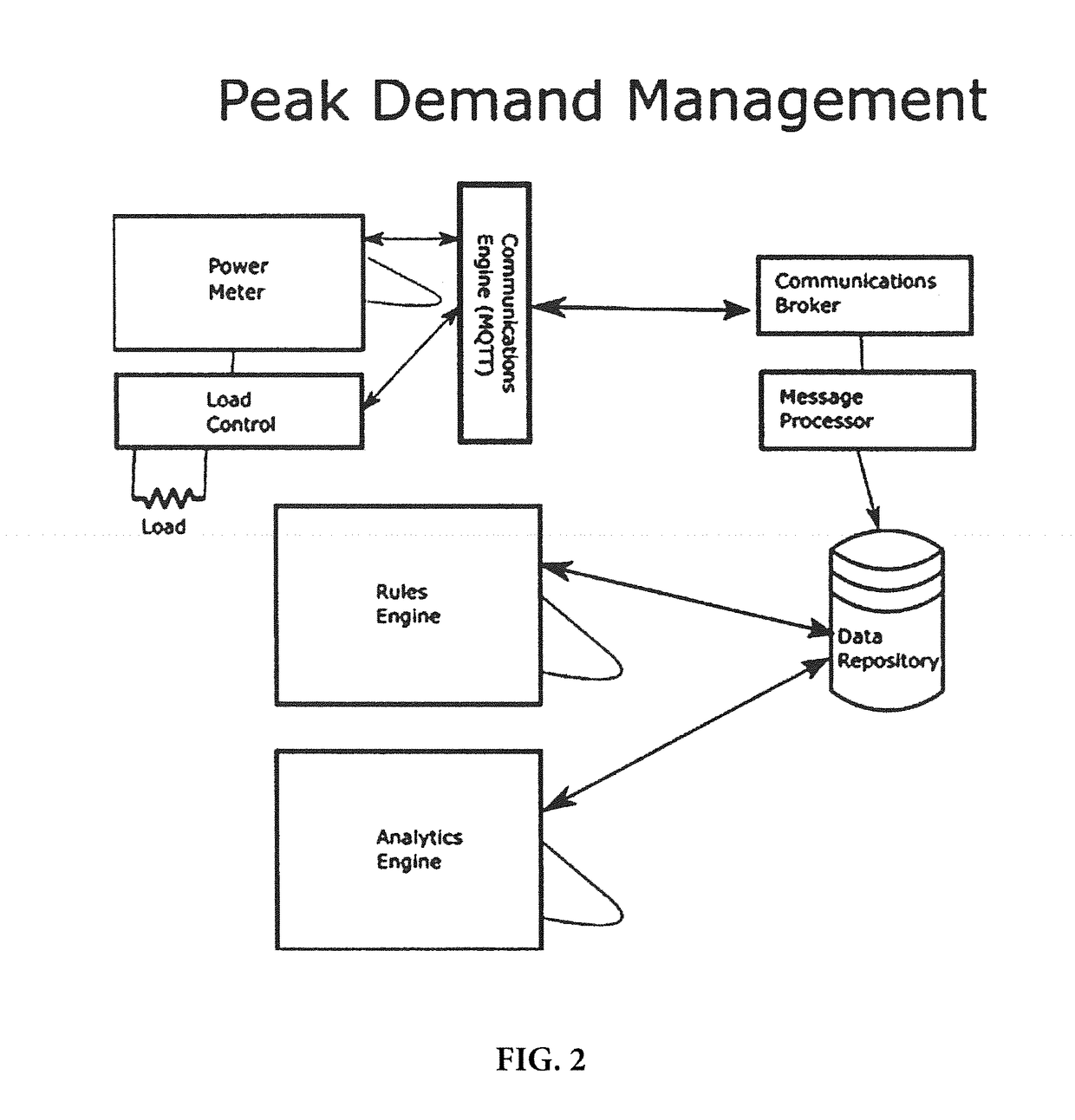
The present invention provides a system that can read and respond to conditions and usage on a much more granular level. The system automatically responds to usage events and / or environment conditions to avoid excessive or elevated expenses. This is achieved by controlling energy usage devices at a facility based on energy usage in comparison to a threshold of energy usage and a control rule. The control input curtails energy usage to avoid the peak demand value of energy usage. The technical effects of the invention are to minimize energy usage, optimize energy usage, and reduce energy costs.

Problems solved by technology

While there may be some benefits in adding a controller to the existing heating configuration, the control and scheduling functions are only limited to the heating and cooling system.
However, in a room with both a Nest thermostat and a WEMO switch, the sensors in the Nest thermostat do not communicate with the WEMO switch.
Further, each of the sensors is purpose built for a single device, meaning the Nest sensor can only work to control the single thermostat to which it is connected.
In the commercial setting, electrical power usage can be a significant expense and it is difficult to determine where usage is occurring.
The difficulty is that the meter that determines if the threshold is surpassed is only able to give usage metrics as to the overall location.

Method used


Image

  • Multi Sensor Pack and Control of Energy Consumption Devices
  • Multi Sensor Pack and Control of Energy Consumption Devices
  • Multi Sensor Pack and Control of Energy Consumption Devices

Examples


Embodiment Construction

[0032]Referring now to the drawings, wherein like reference numerals designate corresponding structure throughout the views. The following examples are presented to further illustrate and explain the present invention and should not be taken as limiting in any regard.

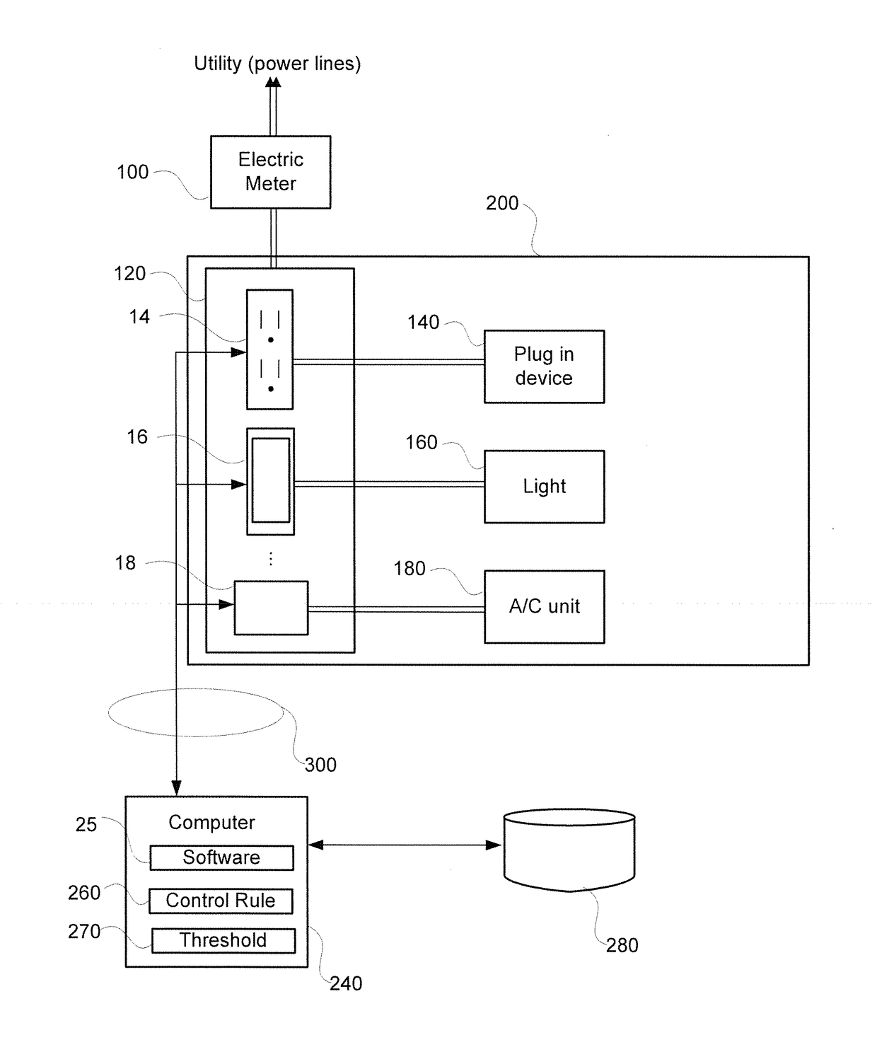
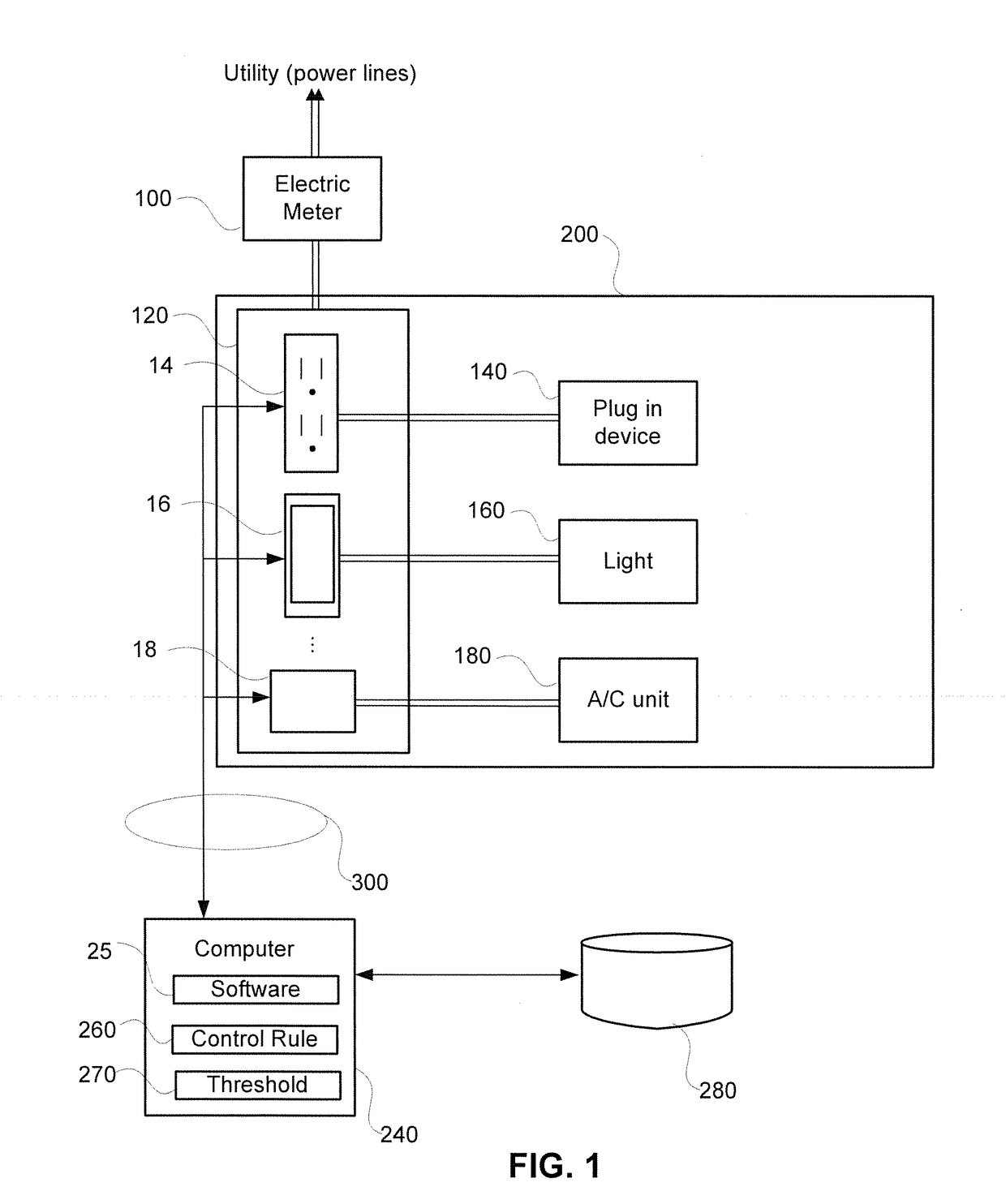
[0033]FIG. 1 shows a facility 200 with a number of electrical energy usage devices 140, 160, 180 connected to adaptors 14, 16, 18. Examples of devices are shown (plug in device, light, air conditioning unit), but it is understood that other electrical devices can be used and those shown are merely exemplary and that many more electrical energy usage devices can be present at the facility 200 downstream of the electric meter 100. The electric meter 100 is typically installed or supplied by or for the benefit of the utility company so that this company can charge the facility the appropriate amount of money for electrical usage. As described below, the way in which charges are made and the rates therefore can change signi...


PUM


Abstract

A system which can curtail energy usage in response to increasing energy demands in order to avoid peak demand or demand based charges using networked adaptors and sensors. In certain aspects, adaptors are in wireless communication with a controller which is configured to monitor usage of the adaptors and control the adaptors as needed to respond to usage events or environmental conditions. A multiple sensor pack may be provided in wireless communication with multiple devices, or adaptors and the controls may be implemented based on readings from the sensors or adaptors or both.

Description

FIELD OF THE INVENTION[0001]The following relates to systems for curtailing energy usage in response to peak usage events as well as a sensor pack and underlying software that enables granular control of electrical power using devices. In addition, the following relates to management of devices via a sophisticated software program and arrangement of hardware devices (IoT) where the devices use the sensor pack and / or include control and measurement features such that energy usage can be controlled on a granular level in response to demand based events.BACKGROUND OF THE INVENTION[0002]Internet of things (IoT) devices are becoming more and more prevalent in both home and commercial settings. For example, thermostats such as the NEST® thermostat are designed to include a thermostat controller, temperature sensor and wifi module all in a single housing that can easily replace existing thermostats that are not “smart” or network enabled. While there may be some benefits in adding a contro...

Claims


Application Information

Patent Timeline
Patent Type & Authority Applications(United States)
IPC IPC(8): H02J13/00G05B15/02
CPCH02J13/0075G05B15/02H02J13/00024H02J13/00026Y04S40/126Y04S20/00Y02B90/20Y02E60/00
Inventor SUBBLOIE, ALBERT
Owner BUDDERFLY INC
Learn More