

Knee joint implant
a knee joint and implant technology, applied in the field of knee joint implants, can solve the problems of increasing the number of patients with incurable knee joints, difficulty in optimal cement technique, and weakening of quadriceps femoris muscle, so as to simplify complex surgical procedures, minimize the delay of recovery, and stabilize the fixing force
- Summary
- Abstract
- Description
- Claims
- Application Information
AI Technical Summary
Benefits of technology
Problems solved by technology
Method used
Image

Examples
Embodiment Construction
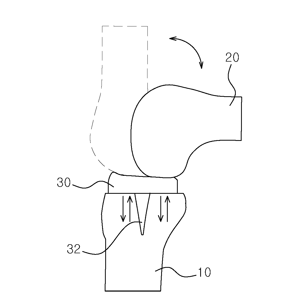
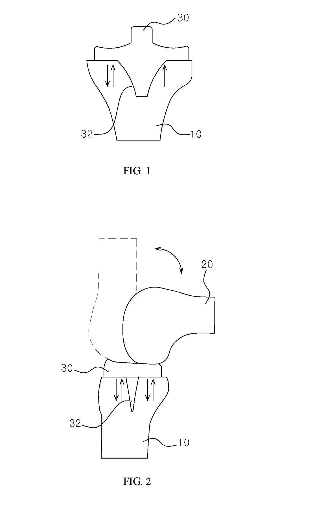
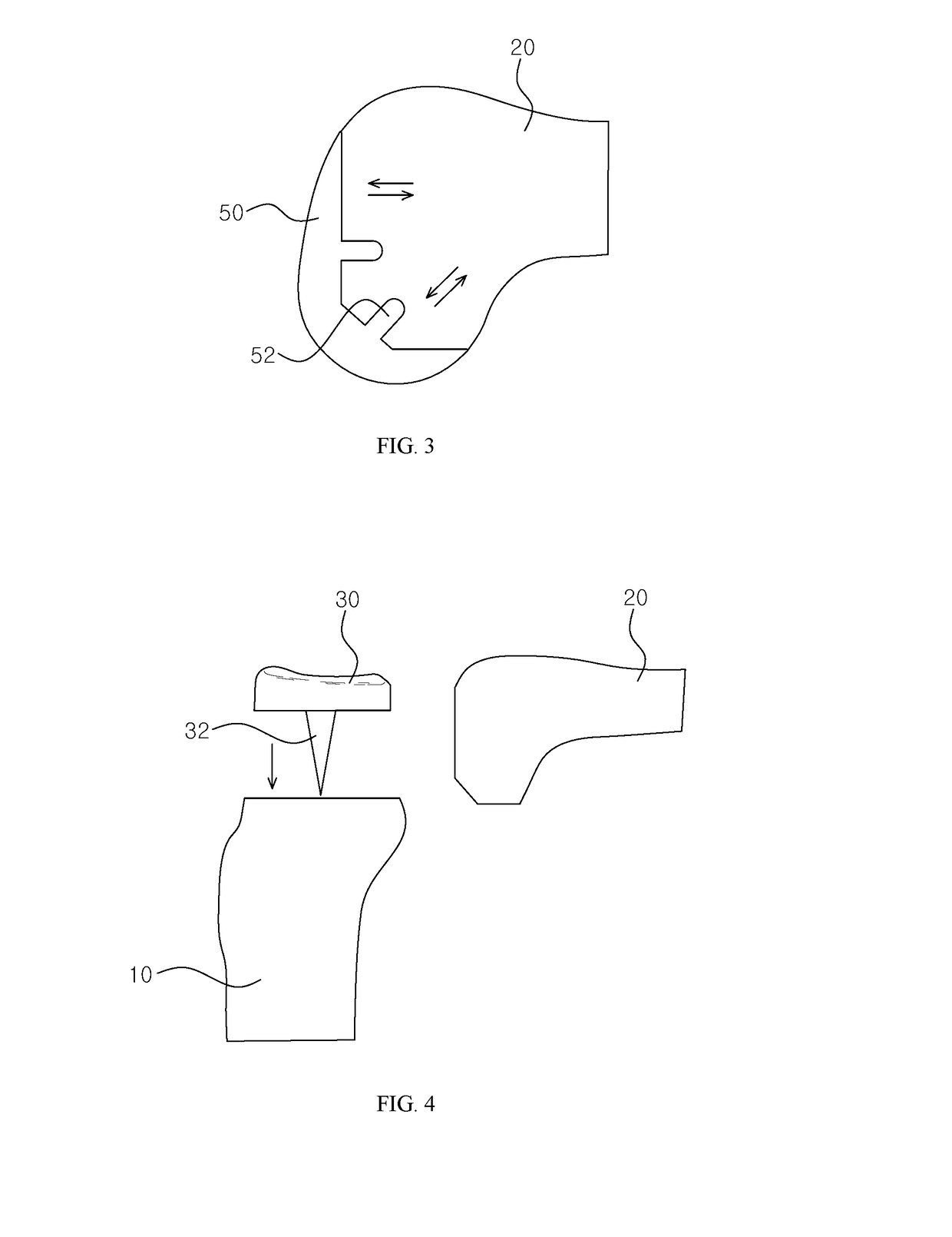
[0095]Hereinafter, a knee joint implant according to the present invention is described in detail. Well-known functions or constructions will not be described in detail in case they may unnecessarily obscure the understanding of the present invention.
[0096]Specific structural and functional descriptions of embodiments of the present invention disclosed herein are only for illustrative purposes of the embodiments of the present invention. The embodiments according to the spirit and scope of the present invention can be variously modified in many different forms. While the present invention will be described in conjunction with exemplary embodiments thereof, it is to be understood that the present description is not intended to limit the present invention to those exemplary embodiments. On the contrary, the present invention is intended to cover not only the exemplary embodiments, but also various alternatives, modifications, equivalents and other embodiments that may be included with...
PUM
 Abstract
Description
Claims
Application Information