Devices for Broken Drill Bit Removal

a drill bit and device technology, applied in the direction of drilling/boring measurement devices, twist drills, manufacturing tools, etc., can solve the problems of increasing the amount of drilling and removal costs, and affecting the accuracy of drilling and drilling. achieve the effect of aggressive spirals and diameters

Inactive Publication Date: 2018-04-12
WOODS RAY FITZGERALD
View PDF22 Cites 5 Cited by
  • Summary
  • Abstract
  • Description
  • Claims
  • Application Information

AI Technical Summary

Benefits of technology

[0022]To alleviate the disadvantages of prior art, a drill bit is provided herein. The present invention comprises utilizing a majority of drill bits on the market used for cutting a hole in various materials such as wood, metal, plastic, concrete, earth and rock. For drills that provide holes in wood, metal, plastic, or concrete; a shank of the drill bit has flats and is used in conjunction with a powered hand drill, drill press, or CNC machine. A body of the drill bit if used for hole drilling in metal, wood, plastic, or concrete contains one or more chip flutes that help remove debri from a cutting tip. Along the outer edge of the flutes can be lips that also cut away material. The cutting tip is at the opposite end from the shank. The cutting tip can be machined on the drill bit or the cutting tip can be made separate of the drill bit and attached to the drill bit. The drill-bit cutting tip can be machined in different shapes and angles. The flutes and lips can be in multiples or singular, have different depths and lengths, and have a more or less aggressive spirals and diameters.

Problems solved by technology

If the aforementioned drill head becomes bound by a rock or dense vein of material the drill pipe can become compromised and break leaving behind the cutting head lodged deep within the earth, which creates a substantial financial loss for the driller.
As one skilled in the art can see this will save the operator from down time and added expense currently required for the tedious removal of a piece of drill bit or completely discarding the component containing the broken piece of drill bit.

Method used


Image

  • Devices for Broken Drill Bit Removal
  • Devices for Broken Drill Bit Removal
  • Devices for Broken Drill Bit Removal

Examples


Embodiment Construction

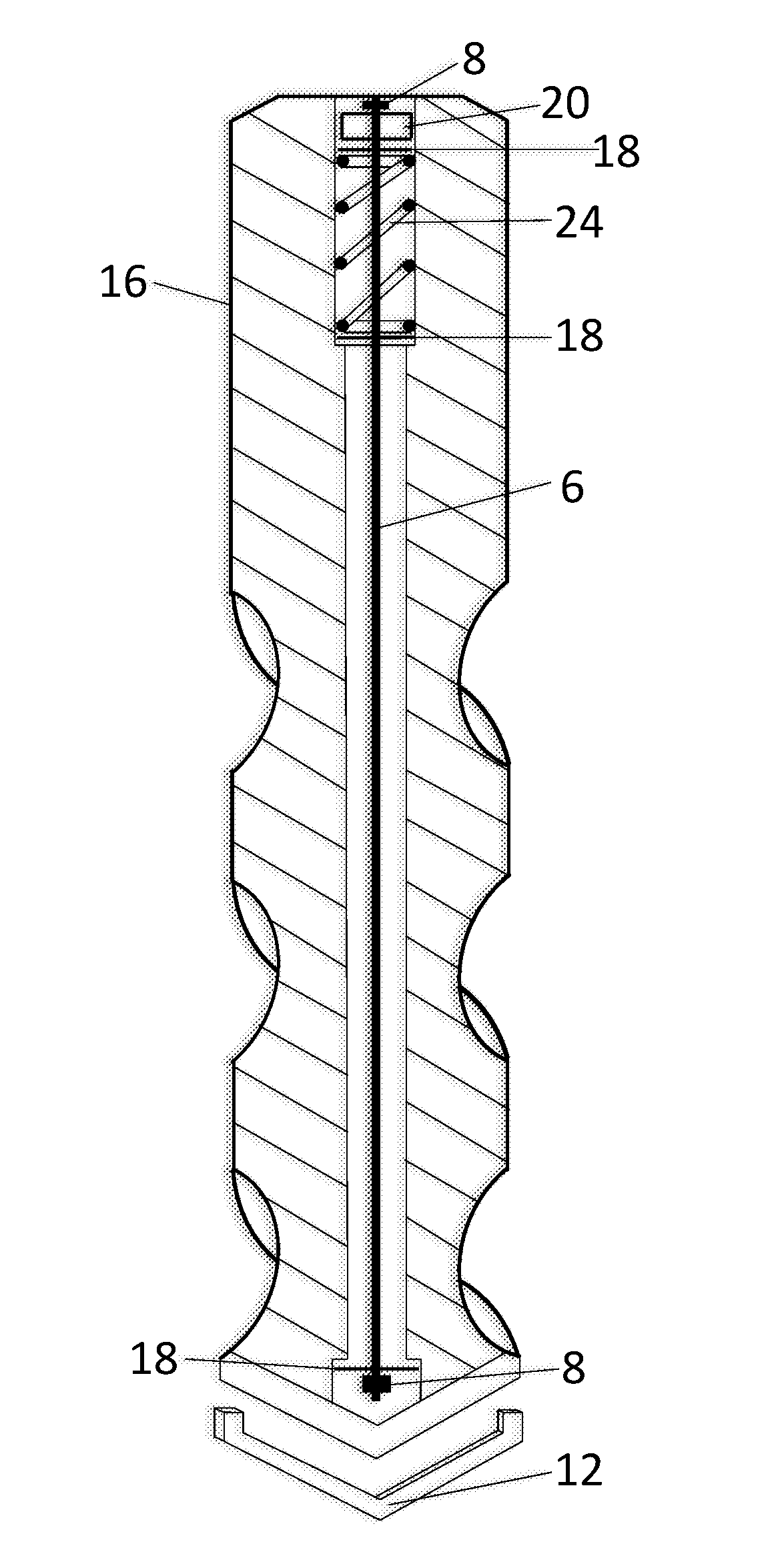
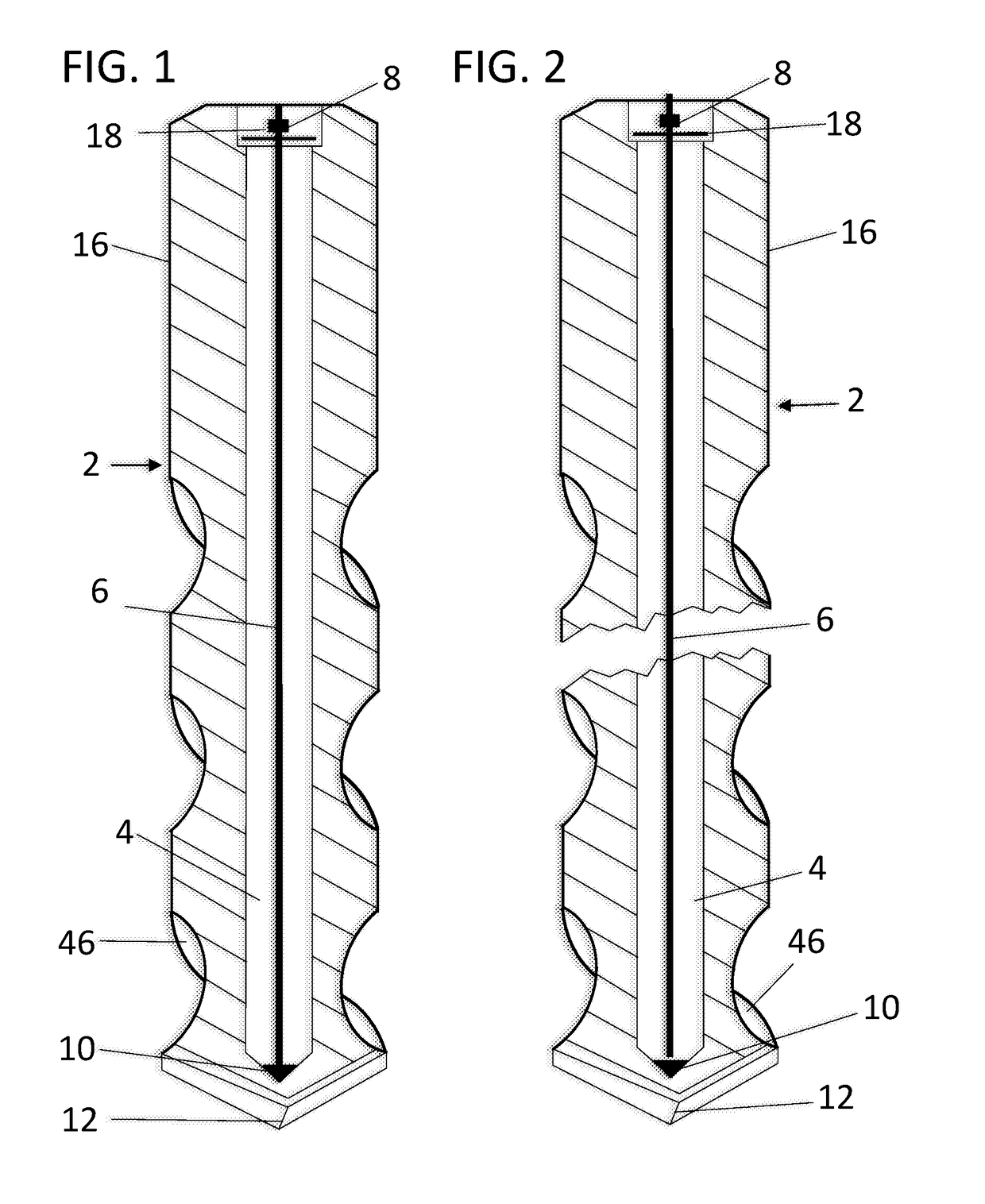
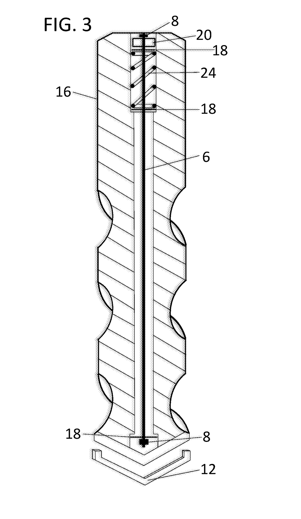
[0034]FIG. 1 shows a drill bit 2 as taught by the current invention, which has a shank 16, at least one chip flute 46, a cutting tip 12, a machined center hole 4, and a wire rope 6 running through the center hole 4. Drill bits 2 are made from metal and undergo a heat-treating process to further strengthen the metal of the drill bit 2. The center hole 4 runs interiorly of the drill bit 2 along a longitudinal axis thereof. It is preferred that the present invention has the center hole 4 machined into the drill bit 2 prior to the heat-treating process but can be machined after the heat-treating process if necessary. The preferred shape of the center hole 4 is round but can be square, hex, and triangular shaped without departing from the spirit of the invention. The shank 16 of the drill bit 2 is adapted with flats to be gripped by a rotary machine (ex. Hand drill, CNC drill etc.) used for drilling, and is a first a end of the drill bit 2, where a larger diameter hole is machined concen...


PUM

PropertyMeasurementUnit
diameteraaaaaaaaaa
lengthaaaaaaaaaa
interior diameteraaaaaaaaaa

Abstract

Devices for broken drill bit removal are provided herein. The drill bit includes a center through hole situated longitudinally and interiorly in the drill bit. A wire rope first end is welded to a cutting tip of the drill bit and retained freely within the walls of the center through hole and said wire rope having a stop attached at a second end. Should the drill bit be compromised, leaving the portion of drill bit head lodged in the bore, the pieces of drill bit are still connected via said wire rope and the lodged portion can be easily and quickly removed by pulling and backing out the powered device that was driving the drill bit thus alleviating the necessity of EDMing the broken drill bit out of the bored component.

Description

CROSS REFERENCE TO RELATED APPLICATIONS[0001]This application claims priority from U.S. Provisional Patent Application No. 62 / 405,911 filed Oct. 8, 2016 with the United States Patent and Trademark Office. The disclosure of which is incorporated herein.BACKGROUND1. Field[0002]The present invention relates to the traditional drill bits and tools of the like used for cutting holes in various materials such as wood, metal, plastic, concrete, rock and earth. The present invention is geared more specifically toward extracting a broken drill bit out of a hole.2. Description of Related Art[0003]Conventional drill bits are defined by length, material, shape, and the material they cut. Drill bits are formed with one or more cutting surfaces, usually formed at the tip of the bit, can have one or more s, and most often made of steel. Drill bits are used for cutting holes in various materials and are driven by drill guns, CNC machines, drill rigs and, in some cases, by hand. In the event the dri...

Claims


Application Information

Patent Timeline
Patent Type & Authority Applications(United States)
IPC IPC(8): B23B51/02
CPCB23B51/02B23B2251/40B23B49/001B23B2251/00B23B2270/20
Inventor WOODS, RAY FITZGERALD
Owner WOODS RAY FITZGERALD
Why Eureka
Try Eureka