Modular block retaining wall system

Active Publication Date: 2018-04-12
LONERO RICHARD PAUL
View PDF3 Cites 4 Cited by
  • Summary
  • Abstract
  • Description
  • Claims
  • Application Information

AI Technical Summary

Benefits of technology

This patent describes a new type of block used in construction that has channels on its surfaces and connectors that allow blocks to be aligned and bonded together. These connectors can slide along the channels to create different levels of bonding. The design allows for custom-made blocks and different degrees of setback. The channels can be formed parallel to the front and rear faces of the blocks, making it easier to build walls with alternating front and rear faces. The connectors can also anchor a geogrid to stabilize the blocks in the upper courses when soil is being retained.

Problems solved by technology

The geogrid stabilizes the blocks in the upper courses, where frictional force between mating surfaces may not be sufficient to stabilize the courses against soil loading.

Method used


Image

  • Modular block retaining wall system
  • Modular block retaining wall system
  • Modular block retaining wall system

Examples


Embodiment Construction

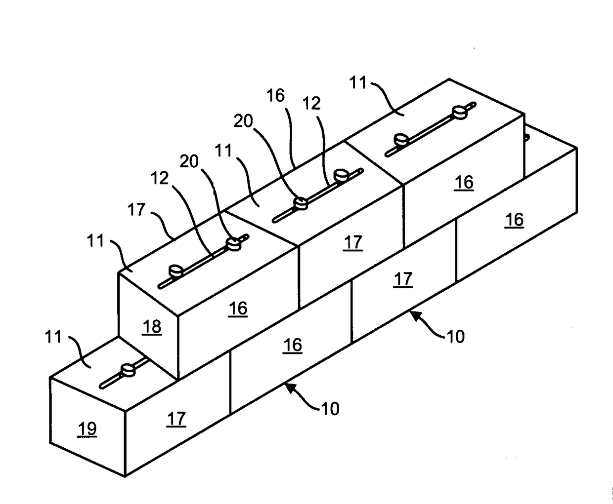
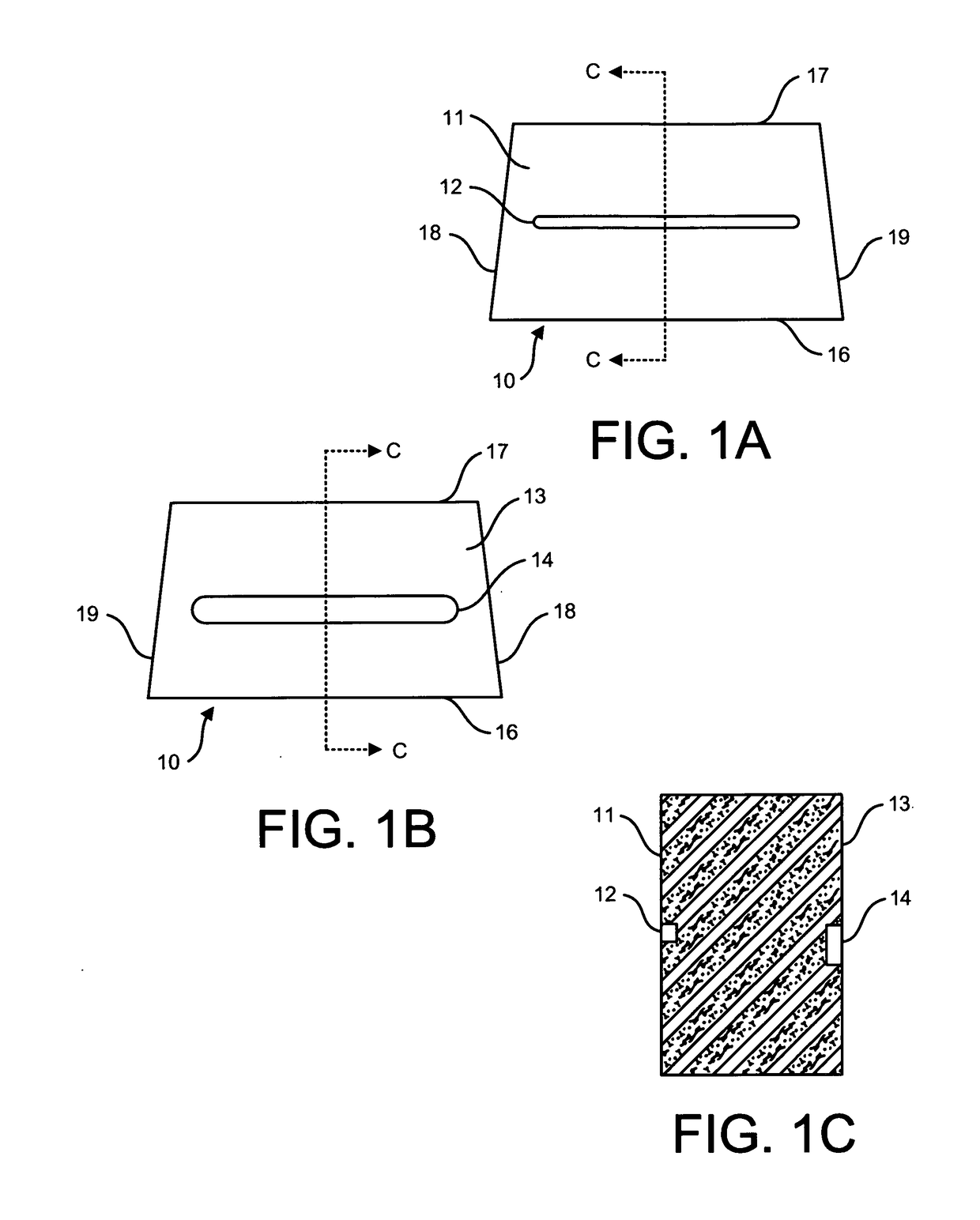
[0052]FIGS. 1A-1C show a trapezoidal modular block 10 according to a first embodiment of the invention. Each block has parallel opposed top and bottom trapezoidal surfaces 11, 13 bounded by parallel opposed front and rear faces 16, 17 and converging end faces 18, 19. As shown in FIG. 1A, a top channel 12 is centered between front and rear faces 16, 17. FIG. 1B shows bottom surface 13 and bottom channel 14, which is wider than top channel 12 and is offset toward front face 16. The channels 12, 13 do not extend to the end faces 18, 19. FIG. 1C illustrates the depth of the top and bottom channels 12 and 14, which are profiled to receive respective first and second portions of a connector. The channels 12, 14 needn't be centered between the front and rear faces 16, 17; the operative factor in determining setback is the offset of the second channel 14 from the first channel 12.

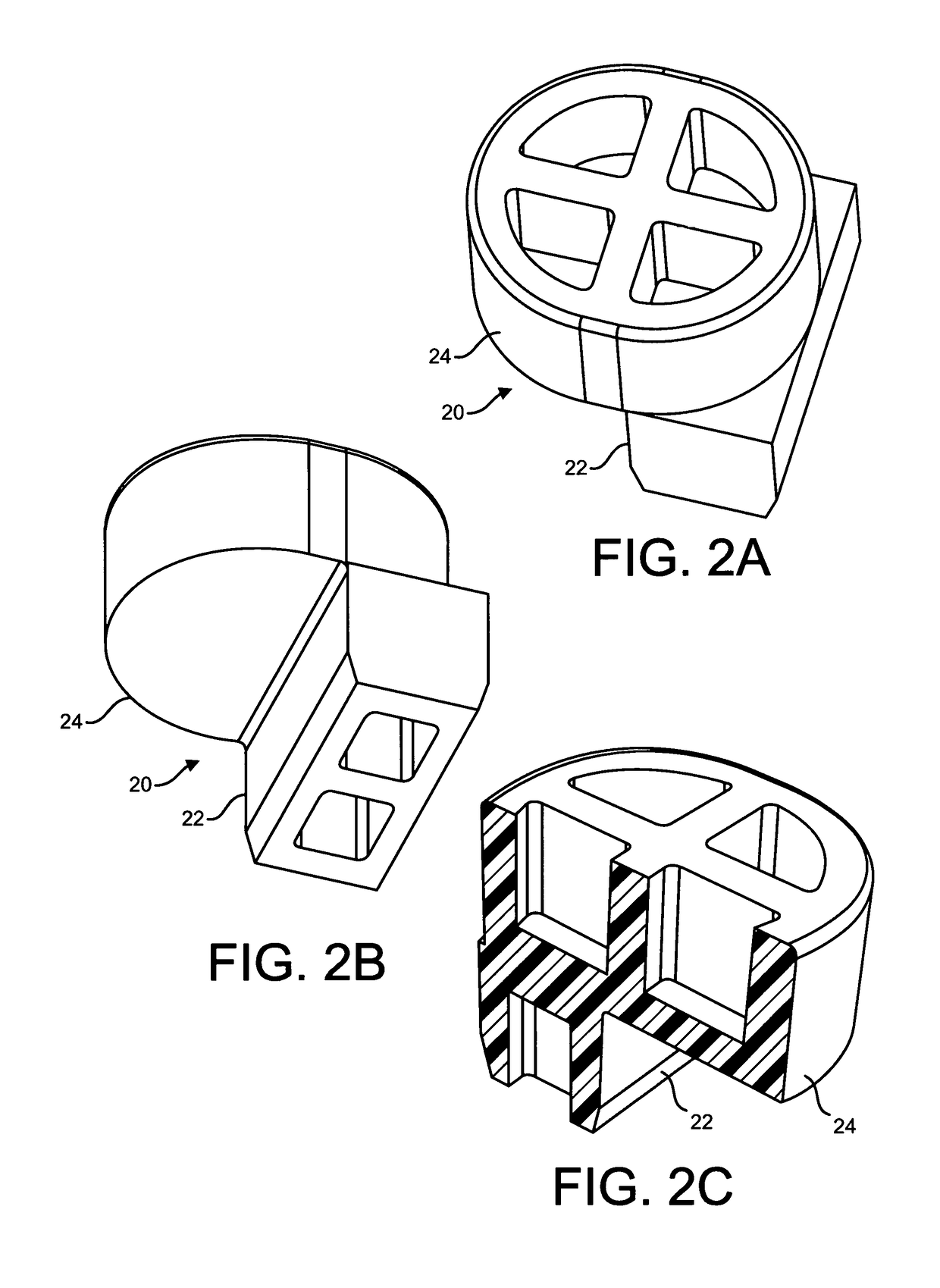
[0053]FIGS. 2A-2C show a preferred embodiment of connector 20 according to the invention, having a rectangular f...


PUM

PropertyMeasurementUnit
Lengthaaaaaaaaaa
Widthaaaaaaaaaa

Abstract

A system for building a wall includes a plurality of blocks and a plurality of connectors for aligning the blocks in successive courses. Each block has opposing first and second surfaces bounded by opposing front and rear faces and opposing end faces, the first and second surfaces being profiled with respective first and second rectilinear channels extending parallel to the front and rear faces. Each connector has first and second portions profiled for reception in respective first and second channels, the first portion being profiled to slide but not rotate in the first channel, the second portion being profiled to slide and rotate in the second channel. The second portion is offset from the first portion so that two different orientations of two blocks placed against each other are possible. The blocks preferably have a trapezoidal shape cut with only straight cuts to facilitate using natural stone.

Description

FIELD OF THE INVENTION[0001]The invention relates to a modular retaining wall system of the type utilizing blocks having channels that receive connectors for aligning and fixing blocks in successive courses in a number of orientations, and further provide means for attaching a soil reinforcing material such as a geogrid.DESCRIPTION OF THE RELATED ART[0002]Walls made of cut stone that is dry stacked, i.e. built without the use of mortar, have been known since ancient times; the Great Wall of China was built in the first millennium BC. Stone walls may be arranged in vertically aligned courses of stones placed end-to-end in rows, or arranged in successive courses that are set back to form a sloped wall for retaining soil or other filling behind the wall.[0003]In recent years, segmental concrete retaining wall units which are dry stacked have become a widely accepted product for the construction of retaining walls. Kiltie Corporation markets its pre-fabricated concrete blocks under the ...

Claims


Application Information

Patent Timeline
IPC IPC(8): E02D29/02E04C1/39E04H17/14
CPCE02D29/0266E02D29/025E04C1/395E04H17/1404E02D29/0233E02D2200/1657E02D2200/1692E02D2250/0023E02D2300/002E04B2002/0245E04B2002/0265B28D1/02B28D1/26
Inventor LONERO, RICHARD PAUL
Owner LONERO RICHARD PAUL
Why Eureka
Try Eureka