

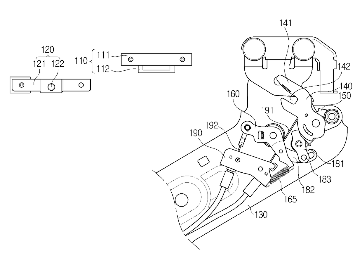
Locking Apparatus for Sliding Door
a technology for locking apparatus and sliding door, which is applied in the direction of door/window fittings, wing accessories, and applications that are used for locking purposes, etc. it can solve the problems of reducing user convenience, sliding door may move in the closing direction and slide shut by itself, and passenger parts may become stuck between the sliding door and the vehicle body, so as to improve safety and convenience of passengers, reduce vehicle weight, and facilitate manufacturing and installation.
- Summary
- Abstract
- Description
- Claims
- Application Information
AI Technical Summary
Benefits of technology
Problems solved by technology
Method used
Image

Examples
Embodiment Construction
[0038]Exemplary embodiments of the present disclosure are described in detail with reference to the accompanying drawings. The same reference numbers are used throughout the drawings to refer to the same or like parts. Detailed descriptions of well-known features and structures incorporated herein may be omitted to avoid obscuring the subject matter of the present disclosure. Other exemplary embodiments or features may further be utilized, and other changes may be made, without departing from the scope of the subject matter presented herein. The exemplary embodiments described herein are not meant to be limiting. Thus, aspects of the present disclosure, as generally described herein and illustrated in the figures, can be arranged, substituted, combined, separated and designed in a wide variety of different configurations, all of which are explicitly contemplated herein.
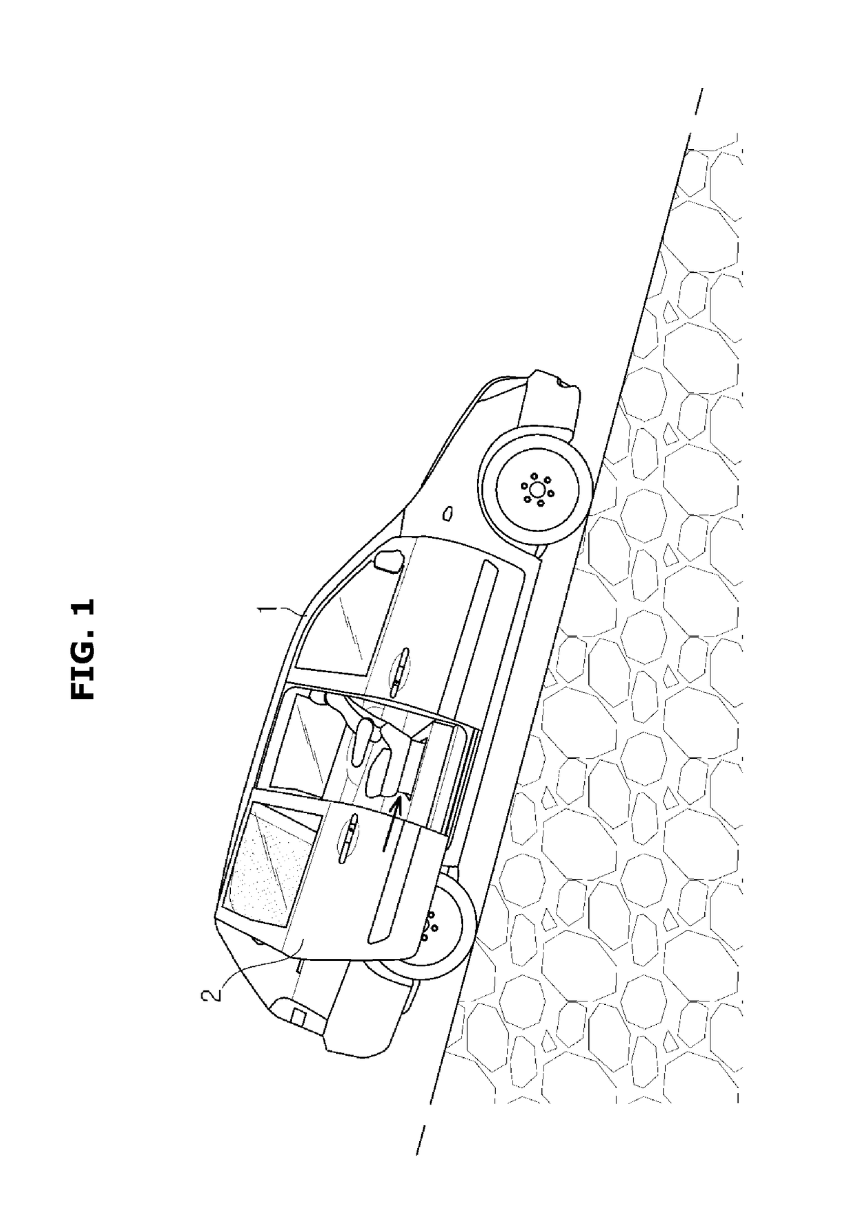
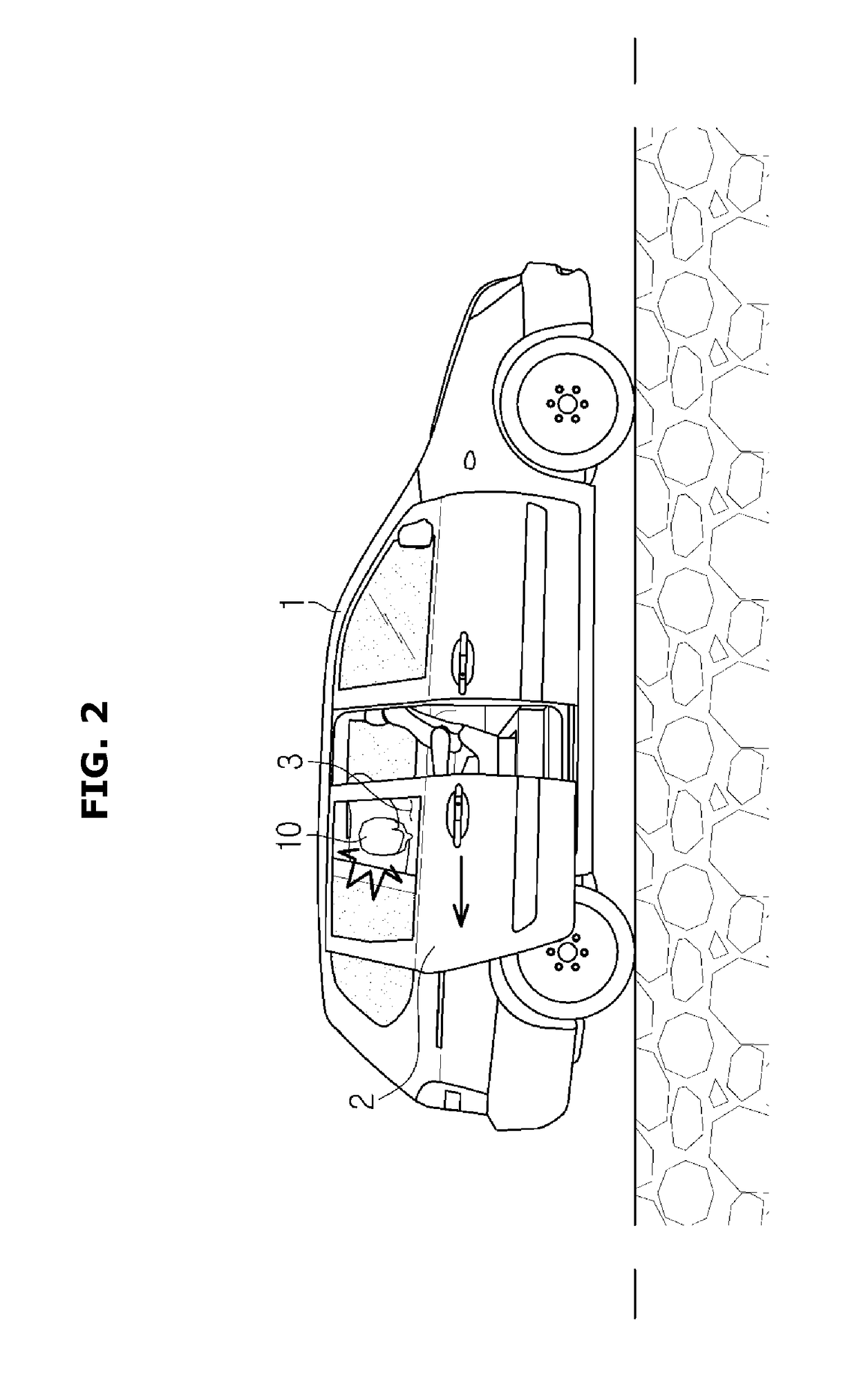
[0039]FIG. 1 depicts a hold-open lock feature of a sliding door 2, and FIG. 2 depicts a glass safety lock feature o...
PUM
 Abstract
Description
Claims
Application Information