Differential limiting device for vehicle

Active Publication Date: 2018-04-12
TOYOTA JIDOSHA KK
View PDF0 Cites 5 Cited by
  • Summary
  • Abstract
  • Description
  • Claims
  • Application Information

AI Technical Summary

Benefits of technology

The invention allows for a compact and efficient differential limiting device that reduces the number of parts and the size of the device. The actuator converts rotary motion into linear motion, preventing differential rotation of the gears. The nut member and screw shaft member rotate smoothly, reducing the electric power needed for the actuator. The actuator is coupled to the screw mechanism through a worm gear, which allows for the use of a low-output actuator.

Problems solved by technology

In the meantime, the differential limiting device for the vehicle as described above has a problem that, during relatively hard, off-road traveling, the frictional engagement elements may slip due to a shortage of the torque capacity of the friction clutch, and burning may occur in the friction clutch.
However, to this end, there is a need to add a mechanism, such as an actuator, for engaging and disengaging the dog clutch, to the differential limiting device, which may result in increase of the size of the differential limiting device.
Therefore, differential rotation of the above pair of side gears is mechanically limited.

Method used


Image

  • Differential limiting device for vehicle
  • Differential limiting device for vehicle
  • Differential limiting device for vehicle

Examples


Embodiment Construction

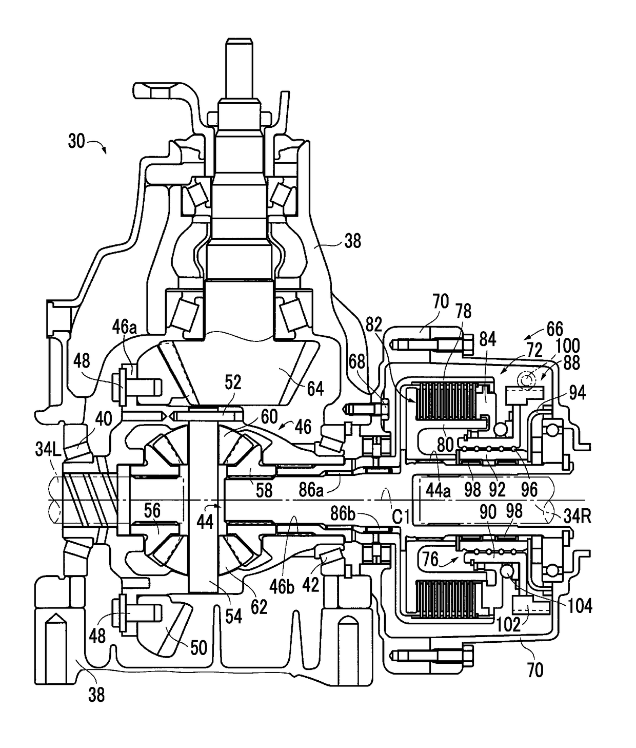
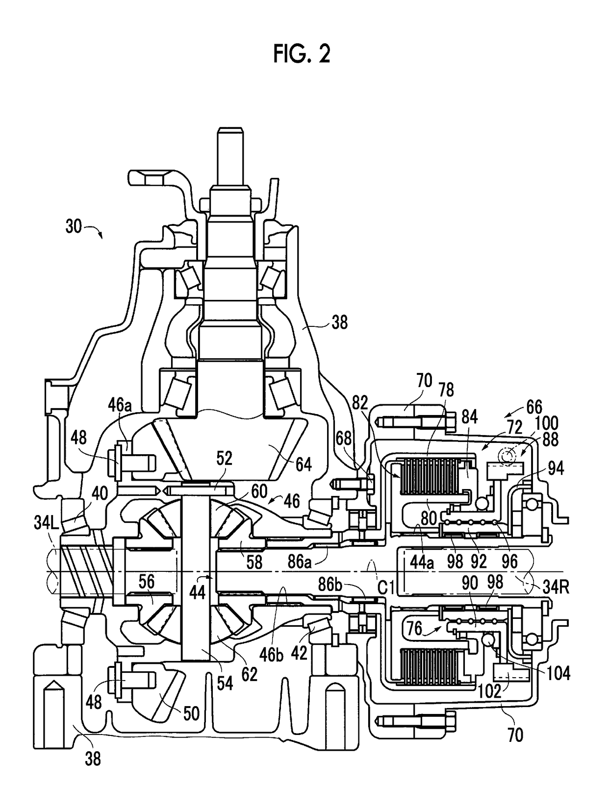
[0027]Some embodiments of the disclosure will be described in detail with reference to the drawings. In the following embodiments, parts or components illustrated in the drawings are simplified or modified as needed, and the ratio of dimensions, shape, etc. of each part or component are not necessarily accurately depicted.

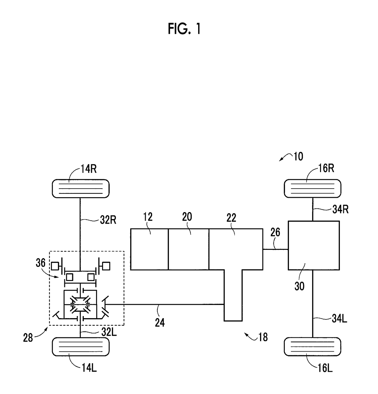
[0028]FIG. 1 shows the general configuration of a vehicle 10 to which the disclosure is applied. The vehicle 10 includes an engine 12 as a drive power source, left and right front wheels 14L, 14R (which will be referred to as “front wheels 14” when they are not particularly distinguished), left and right rear wheels 16R, 16L (which will be referred to as “rear wheels 16” when they are not particularly distinguished), a power transmission system 18 that transmits power of the engine 12 to the front wheels 14 and the rear wheels 16, respectively, and so forth. The rear wheels 16 are primary drive wheels that serve as drive wheels during traveling in a two-wheel drive...


PUM


Abstract

In a differential limiting device for a vehicle, when rotary motion of an electric motor is converted by a screw mechanism into linear motion of a nut member in a direction of a first axis C1 of a side gear shaft, and a piston mounted on the nut member is moved in a direction opposite to a direction to depress frictional engagement elements, the piston and a clutch drum are relatively non-rotatably engaged. Therefore, differential rotation of a pair of side gears is mechanically limited. Thus, rotation of one electric motor makes it possible to generate differential limiting torque for limiting differential rotation of the pair of side gears in a rear-wheel differential device.

Description

INCORPORATION BY REFERENCE[0001]The disclosure of Japanese Patent Application No. 2016-198545 filed on Oct. 6, 2016 including the specification, drawings and abstract is incorporated herein by reference in its entirety.BACKGROUND1. Technical Field[0002]The disclosure relates to a differential limiting device for a vehicle, which limits differential rotation of a pair of side gears provided in a differential device, and is particularly concerned with a technology for favorably reducing the size of the differential limiting device for the vehicle.2. Description of Related Art[0003]For example, a differential limiting device for a vehicle, which limits differential rotation of a pair of side gears provided in a differential device, is known. One example of the differential limiting device for the vehicle is described in U.S. Patent Application Publication No. 2002 / 0032096. The differential limiting device for the vehicle described in this publication includes a friction clutch having a...

Claims


Application Information

Patent Timeline
IPC IPC(8): F16H48/22F16D13/52F16H25/22F16D23/00B60K17/344B60K17/02F16H48/08F16H48/34
CPCF16H48/22F16D13/52F16H25/2204F16D23/00B60K17/344B60K17/02F16H48/08F16H48/34F16H2025/209F16H1/16F16H2048/343F16D23/12F16D2023/123F16D2125/52F16H48/24F16H25/22F16D47/00
Inventor IMAFUKU, MIZUKI
Owner TOYOTA JIDOSHA KK
Why Eureka
Try Eureka