
Electrical time measuring system or device indicating time intervals by regioned concentric arciforms that indicate the time of duration of particular events

a technology of electric time measuring and time intervals, applied in the field of electric powered systems or devices for measuring time, to achieve the effect of reducing processor cycle and memory usage and conserving processor cycles and memory usag

Active Publication Date: 2018-04-12
SAMRAT SOLUTIONS INC
View PDF8 Cites 6 Cited by
  • Summary
  • Abstract
  • Description
  • Claims
  • Application Information

AI Technical Summary

Benefits of technology

The patent describes an electrical time measuring device that uses regioned concentric arcforms to indicate the time of duration of events. The device includes a computer system with a processing system and a user interface controller. The device can be used in a computer system to conserve processor cycles and memory usage when indicating time intervals. The device includes a first clockface display and a plurality of concentric regions including an ante meridiem events region and a post meridiem events region. The device also includes logic and a user interface controller to implement a user interface with the first clockface display. The technical effect of this patent is to provide an efficient and effective way to measure electrical time intervals using a computer system.

Problems solved by technology

It is unnecessary, however, for the inventive concept, that an actual user ever interact with the user interface.
It is also unnecessary, for the inventive concept, that an interaction with the user interface be performed by an actual user.

Method used


Image

  • Electrical time measuring system or device indicating time intervals by regioned concentric arciforms that indicate the time of duration of particular events
  • Electrical time measuring system or device indicating time intervals by regioned concentric arciforms that indicate the time of duration of particular events
  • Electrical time measuring system or device indicating time intervals by regioned concentric arciforms that indicate the time of duration of particular events

Examples


example environment

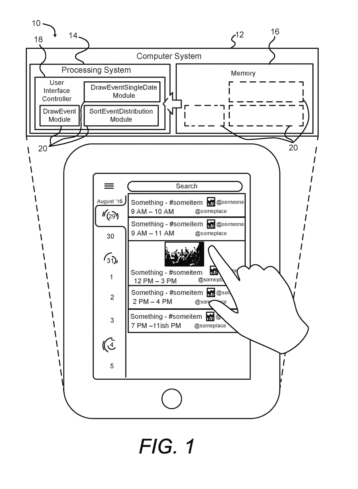
[0075]FIG. 1 illustrates an example computing environment in which an embodiment of the invention is implemented. In FIG. 1, ETMD 10 is a handheld tablet computer equipped with, e.g., a touch-sensitive screen. FIG. 1 also includes a simplified, schematic representation of the ETMD as a computer system 12. Computer system 12 includes a processing system 14, a memory 16, and logic 20.

[0076]The processing system 14 includes, in one example implementation, a hardware processor. If the implementation is on a device such as an APPLE IPAD PRO, for example, the hardware processor is at the present time an A9X processor or similar, which itself contains multiple central processing unit (CPU) cores, and several graphics cores, and various levels of cache memory and numerous buffers. Other modern computer systems include other processing systems of other configurations. The hardware processor has a clock function that keeps time. The clock function of the hardware processor is conventional.

[00...

example embodiment

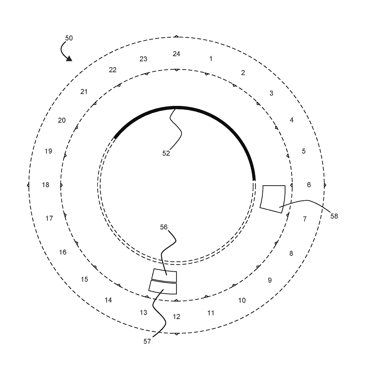
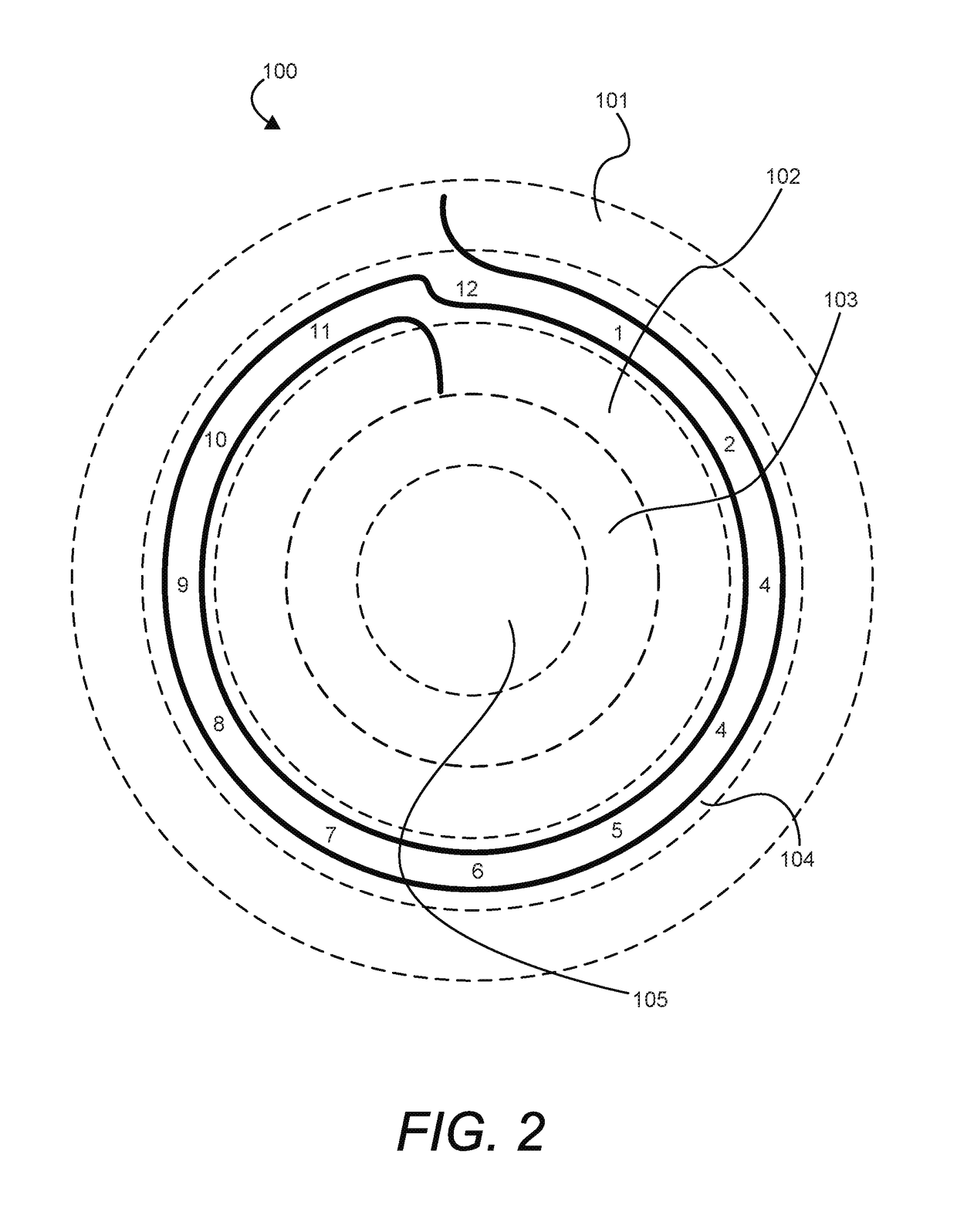
[0083]FIG. 2 is an embodiment of a clockface 100 with a plurality of concentric regions (three in this example) to display arciforms as abstracted events in an easy to understand graphical display. In various embodiments, the three concentric regions are nested so that regions are either completely inside or completely outside each other. In other embodiments that are discussed further below, the concentric regions are nested in fewer than three dimensions, and do not necessarily reside completely inside or completely outside one another.

[0084]The clockface 100 is also referred to herein as a clockface display. The clockface 100 contains any number of nested concentric regions alternating between a.m. and p.m. In this example embodiment, the outermost region contains a.m. events for a particular day and is an ante meridiem events region 101 (a.m. events region). The next inner region contains p.m. events for that day and is a post meridiem events region 102 (p.m. events region). Thi...

example application

Programming Interface (API)

[0143]A partial API suitable for implementing the above-identified embodiments is now described. This API is provided for instruction and as an example, and not by way of limitation. It is to be understood that the example API represents an algorithm for implementing the subject matter of the invention. The example API is implemented, in one example, in software. In other examples, the API is implemented in hardware. In still other examples, the API is implemented partly in hardware and partly in software.

Interfaces

[0144]

TABLE ONEIn-InterfacePermissionsstancesCommentsAggregationRead / Write1The main API database whichDatabasestores Events, Event details, andrelated Social media posts, peruser aggregated from theCalendar and Social MediaDatabasesSocial MediaRead1 . . . nDatabases from sites such asDatabases(Required) / Facebook, Twitter, Instagram,Writeetc.(Optional)CalendarRead1 . . . nDatabases from calendars suchDatabases(Required) / as Google Calendar, iCalen...


PUM


Abstract

An electrical time measuring device, intended to conserve processor cycles and memory when used in indicating time interval durations, includes a computer system with a processing system having a hardware processor and a memory accessible to the processing system, a user interface controller under control of the processing system, and logic, under control of the processing system. Various embodiments include nested concentric regions in a clockface display, an ante meridiem events region, a post meridiem events region, and / or a following-day events or tasks region. Events or time interval durations are represented as arciform. For events that cross from morning to afternoon, or from evening to the following day, arciforms are displayed with a start point in one of the nested concentric regions and an end point in a different one of the nested concentric regions. The parts of such arciforms are joined by an integral boundary-crossing transition indicator.

Description

BACKGROUNDField[0001]This paper discloses a novel electrically powered system or device for measuring time, namely, a system or device that serves as a timepiece or a time measurement apparatus. The system or device uses regioned concentric arciforms to indicate the time of duration of an event.Background and Related Art[0002]Electrically powered / electronic devices for measuring time include computer-based wearables such as wristwatches and computer glasses, virtual reality headsets, mobile devices such as cell phones and media players, tablets, laptop computers, desktop computers, and any computing device regardless of form factor. These modern devices are clock driven, and have the capability to indicate the time of duration of events such as appointments, vacations, schedules.[0003]For simplicity, the foregoing devices are referred to in a general sense as electrically-powered time measuring devices (ETMDs). ETMDs typically have a calendar program that measures time and, as vario...

Claims


Application Information

Patent Timeline
IPC IPC(8): G04G99/00G04G9/00
CPCG04G99/006G04G9/0064G06F17/30286H04W4/025G04G9/02G06F16/20
Inventor DUDHAT, SAMRAT
Owner SAMRAT SOLUTIONS INC
Learn More