
Wireless power transmission device

a power transmission device and wireless technology, applied in the direction of electric variable regulation, process and machine control, instruments, etc., can solve the problems of power control malfunction, waveform of output signal, increasing cost, etc., to reduce the mutual influence of power transmission and stable power transmission and signal transmission simultaneously

Active Publication Date: 2018-04-12
TDK CORPARATION
View PDF5 Cites 5 Cited by
  • Summary
  • Abstract
  • Description
  • Claims
  • Application Information

AI Technical Summary

Benefits of technology

The objective of this invention is to minimize the impact of power transmission on signal transmission, and to ensure that both power and signals can be transmitted simultaneously without interference.

Problems solved by technology

However, in the technology disclosed in JP 2011-223860A, the frequency of the output signal transmitted from the transmitting coil varies with a change in the magnitude of the signal frequency, so that when the frequency of the output signal coincides with a noise frequency component of power transmission drive frequency, the waveform of the output signal is distorted, which may result in power control malfunction, and therefore, there is room for improvement in this respect.
However, a complicated circuit configuration is required to highly accurately control the duty ratio, thus increasing cost due to an increase in the number of parts and posing a problem in reliability.

Method used


Image

  • Wireless power transmission device
  • Wireless power transmission device
  • Wireless power transmission device

Examples


Embodiment Construction

[0015]Preferred embodiments of the present invention will now be explained in detail with reference to the drawings.

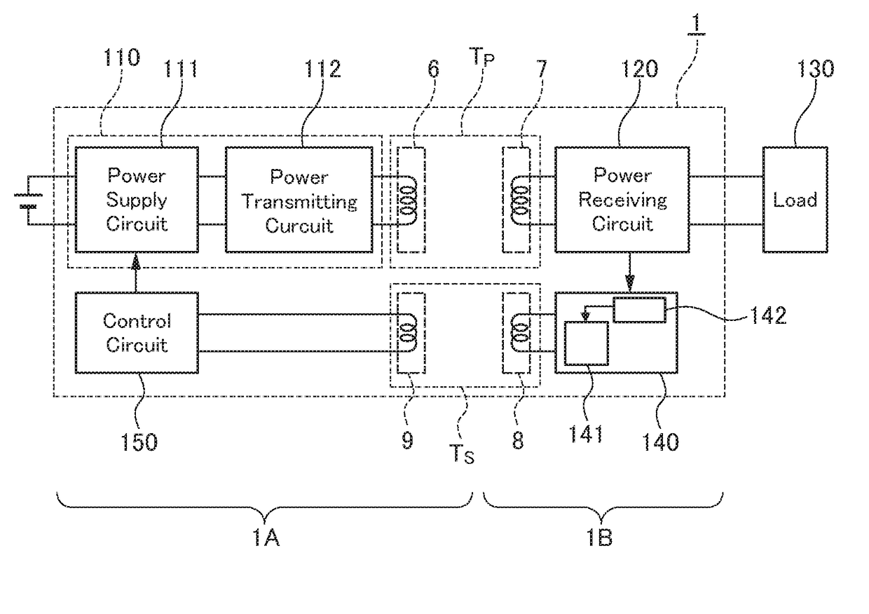
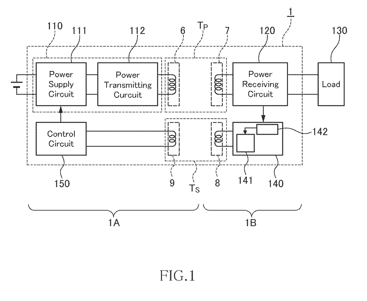
[0016]FIG. 1 is a block diagram schematically illustrating a configuration of a wireless power transmission device according to an embodiment of the present invention.

[0017]As illustrated in FIG. 1, a wireless power transmission device 1 is constituted of a combination of a power transmitting unit 1A and a power receiving unit 1B. The wireless power transmission device 1 is configured to transmit electric power from the power transmitting unit 1A to the power receiving unit 1B by wireless.

[0018]The power transmitting unit 1A includes a power transmitting circuit 110, a power transmitting coil 6, a signal receiving coil 9, and a control circuit 150. The power transmitting circuit 110 converts an input DC voltage into an AC voltage of, e.g., 100 kHz and outputs it. The power transmitting coil 6 generates an AC magnetic flux using the AC voltage. The signal receiving coil...


PUM


Abstract

Disclosed herein is a wireless power transmission device includes a power transmitting transformer coupled between a power transmitting circuit and a power receiving circuit, and a signal transmitting transformer coupled between a signal generating circuit provided at the power receiving circuit side and a control circuit provided at the power transmitting circuit side. The frequency of an AC signal transmitted by the signal transmitting transformer is equal to or more than ten times the frequency of an AC voltage transmitted by the power transmitting transformer. The signal generating circuit converts the magnitude of the output voltage or output current of the power receiving circuit into a magnitude of an amplitude of the AC signal.

Description

BACKGROUND OF THE INVENTIONField of the Invention[0001]The present invention relates to a wireless power transmission device.Description of Related Art[0002]A wireless power transmission technology that feeds power without using a power cord or cable is now attracting attention. The wireless power transmission technology allows wireless power transmission from a power feeding side to a power receiving side and is thus expected to be applied to various products including transport machines such as electric train and electric cars, home electric appliances, electronic devices, wireless communication devices, toys, and industrial appliances.[0003]In order to stabilize an output state on the power receiving side in such a wireless power transmission technology, it is necessary to feed back output information on the power receiving side to the power feeding side and to control AC power to be fed to a power feeding coil based on the output information. As a method for transmitting the out...

Claims


Application Information

Patent Timeline
IPC IPC(8): H02J50/10H02M3/335
CPCH02J50/10H02M3/33576H02J7/025H02J50/12H02M3/00H02M7/06H02J50/80
Inventor HANABUSA, KAZUYOSHIURANO, TAKASHI
Owner TDK CORPARATION
Learn More