Magnetic-controlled generator with built-in controller

a generator and controller technology, applied in the direction of motor/generator/converter stopper, dynamo-electric converter control, shape/form/construction, etc., can solve the problems of wire configuration for installation and not being a good choice for small devices, and achieve fast and stable operation, low manufacturing cost, and small volume

Active Publication Date: 2018-04-12
CHI HUA FITNESS
View PDF0 Cites 9 Cited by
  • Summary
  • Abstract
  • Description
  • Claims
  • Application Information

AI Technical Summary

Benefits of technology

[0008]A primary objective of the present invention is to provide a magnetic-controlled generator with built-in controller that generates electricity and has a magnetic resistance loading device, making it suitable for small training machines with small volume and low costs in manufacturing.
[0009]Another objective of the present invention is to provide a magnetic-controlled generator with built-in controller that integrates a controller, a power generator and a magnetic resistance structure, so as to overcome the difficulties in installation of the controller and configuration of the wires.
[0011]Still another objective of the present invention is to provide a magnetic-controlled generator with built-in controller that employs both linear and quadratic regression analysis in torque calibration to accelerate the calibration process and provide more stability.
[0015]With the structure disclosed above, the present invention provides a device with dual function of power generation and reluctance that has small volume and low costs in manufacturing. Also, the integrated design of power generator with magnetic resistance structure, control circuit unit and calibration software excludes the needs of spaces for installation of the controller and configuration of the wires. The calibration software further enables direct torque calibration with faster and more stable operation by regression analysis models.

Problems solved by technology

However, the structures produce high power of electricity with large magnetic resistance and are therefore suitable for large devices only.
It would not be a good choice for small devices.
The controller used to connect from the outside via circuit modules; therefore the training machines would not have a space designed for the controller, and there are problems of configuration of wires for installation.

Method used


Image

  • Magnetic-controlled generator with built-in controller
  • Magnetic-controlled generator with built-in controller
  • Magnetic-controlled generator with built-in controller

Examples


Embodiment Construction

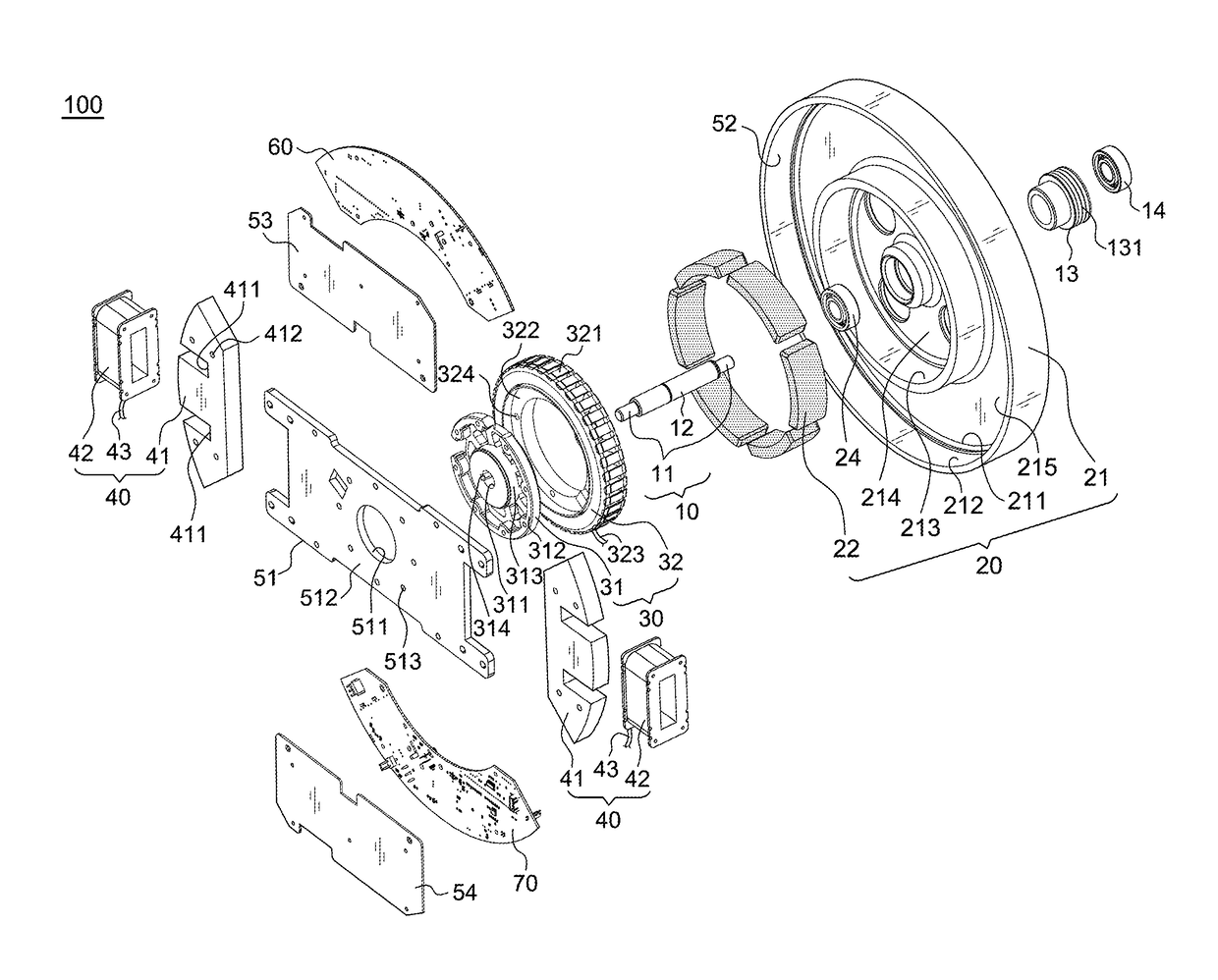
[0029]Referring to FIGS. 3-6, a preferred embodiment of the present invention mainly comprises a shaft 10, a transmission element 13, an outer rotor 20, an inner stator 30, a pair of reluctance devices 40, an engaging element 51, a magnetic ring 52, a control circuit unit 60, a software 65 for torque calibration, and a wireless transmission unit 70.

[0030]The shaft 10 has a middle section 12 and two engaging ends 11 to be fixedly engaged a supporting seat of a training machine.

[0031]The transmission element 13 has a function of receiving the force from the training machine. In this embodiment, the transmission element 13 is a pulley, having a grooved rim 131 for a cord to engage and thus connecting to the training machine; a first bearing hole 132 is arranged for engaging a bearing 14 and being mounted on either of the engaging ends 11, and the bearing 14 is fixed by a C ring 15 so that the pulley 13 is able to rotate on the shaft 10.

[0032]The outer rotor 20 includes a flywheel 21 an...


PUM


Abstract

Disclosed is a magnetic-controlled generator with built-in controller that has integrated design of power generator with magnetic resistance and control circuit unit. The built-in control circuit unit is electrically connected to an armature core, an external digital operator, and a magnetic coil, in order to convert AC power produced by the armature core into DC power to supply for the magnetic coil and meanwhile control the resistance of a flywheel by inserting a number of torque value to the external digital operator. In addition, a software is built inside the generator for instant torque calibration without connecting to extra devices. In application to training machines, the device is easy to be installed and operated without restrictions in extra spaces for a controller and configuration of wires.

Description

[0001]This patent application is a continuation-in-part of Ser. No. 14 / 825,282 filed on Aug. 13, 2015, currently pending.BACKGROUND OF THE INVENTION1. Field of the Invention[0002]The present invention relates to a magnetic-controlled generator, particularly to one that is applied to training machines with a built-in control unit to integrate a power generator with a magnetic resistance structure.2. Description of the Related Art[0003]Many training machines have a flywheel to support the inertia of rotation, and the flywheel can be the loading for training. Recently, a structure of having a flywheel with a permanent magnet as a rotor and an armature as a stator is commonly applied. It has a stator coil producing AC currents for controlling and brake loading. Such structure has been disclosed in U.S. Pat. No. 6,084,325 as shown in FIGS. 1A and 1B and in U.S. Pat. No. 7,732,961 as shown in FIG. 2.[0004]In FIGS. 1A and 1B, a flywheel 820 is rotated by a rotary wheel A. A permanent magne...

Claims


Application Information

Patent Timeline
Patent Type & Authority Applications(United States)
IPC IPC(8): H02K11/33H02K7/02H02K24/00H02K1/27H02K1/12H02K11/00
CPCH02K11/33H02K7/02H02K24/00H02K1/2786H02K1/12H02K11/0094A63B21/0051A63B21/0053A63B21/225A63B22/0605A63B24/0087H02K21/222H02K7/104H02K7/1861A63B2024/0093A63B2220/54A63B2225/50B60L2210/30H02K49/043H02K11/35H02P3/18H02P3/24A63B2209/08Y02T10/64Y02T10/72H02K1/2791
Inventor LEE, YING-CHE
Owner CHI HUA FITNESS
Why Eureka
Try Eureka