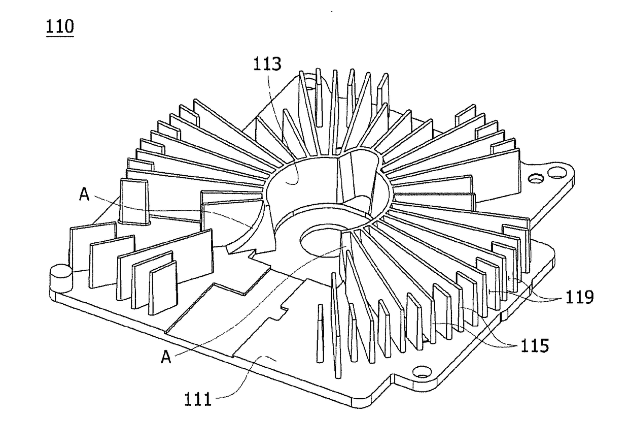
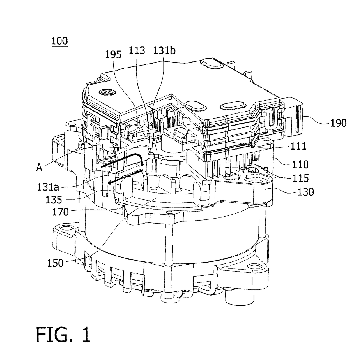
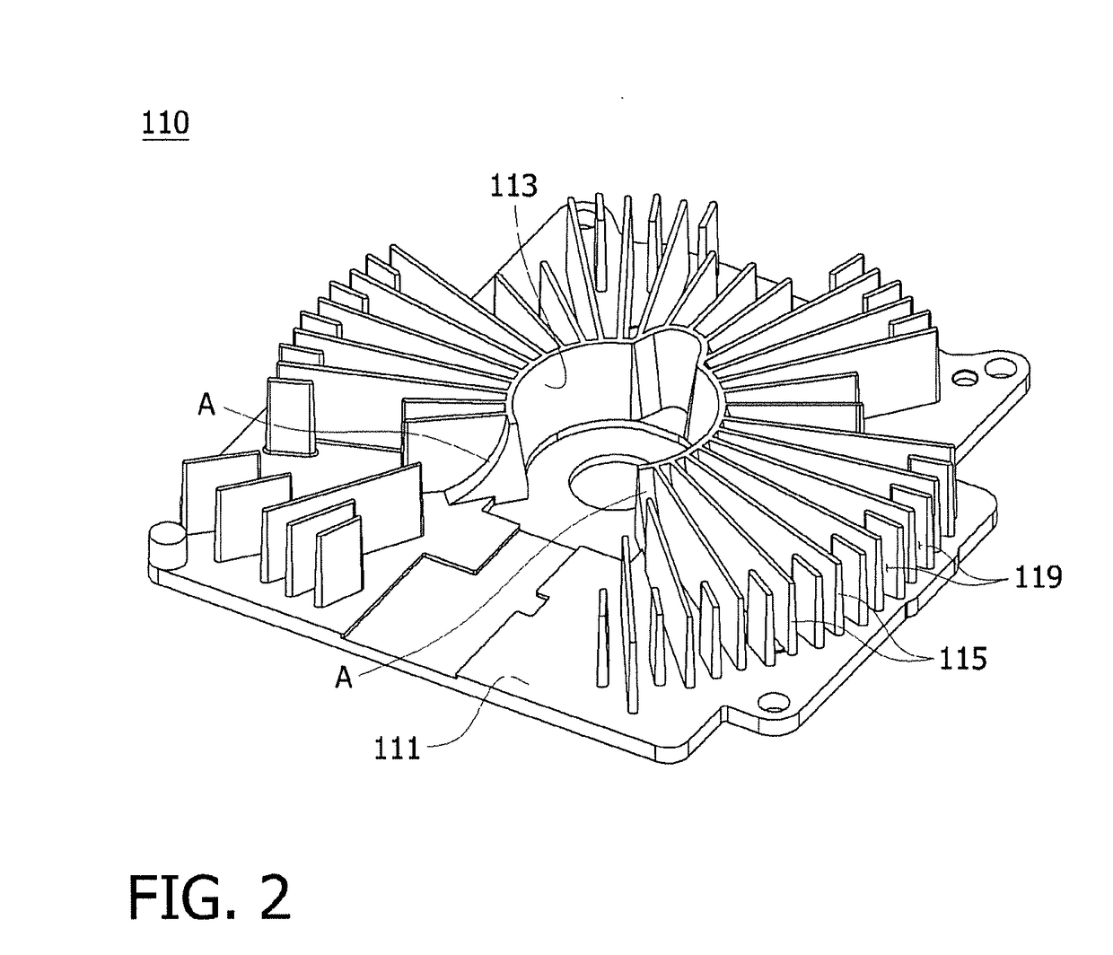
Heat sink assembly

a technology of heat sink and assembly, which is applied in the direction of cooling/ventilation/heating modification, electrical apparatus, dynamo-electric machines, etc., can solve the problems of thermal damage to the circuit elements of the inverter, increased size of the inverter, and relatively serious problems, so as to minimize reduce the size of the inverter, and reduce the effect of the inverter

Inactive Publication Date: 2018-04-12
HL MANDO CORP
View PDF3 Cites 1 Cited by
  • Summary
  • Abstract
  • Description
  • Claims
  • Application Information

AI Technical Summary

Benefits of technology

[0013]Various aspects of the present disclosure provide a heat sink assembly capable of efficiently dissipating heat from circuit elements of an inverter provided above a heat sink.
[0014]Other aspects of the present disclosure provide a heat sink assembly capable of minimizing the size of an inverter and integrating circuit elements into the minimized inverter.
[0015]Yet other aspects of the present disclosure provide a heat sink assembly capable of simplifying a closed structure of an inverter, thereby efficiently preventing the introduction of moisture into the inverter.
[0024]As set forth above, external air is continuously supplied to the body part between the heat sink fins, having an effect of efficiently cooling circuit elements disposed above the heat sink plate.
[0025]Further, there is no need to provide a through-hole in the center of the inverter to cool the circuit elements of the inverter, having effects of minimizing the size of the inverter and of integrating the circuit elements into the minimized inverter.
[0026]Furthermore, the closed structure of the inverter is simplified, having an effect of efficiently preventing the introduction of moisture into the inverter.

Problems solved by technology

In the meantime, a great amount of heat is generated when the inverter converts AC power into DC power, so that the circuit elements in the inverter may be thermally damaged.
However, the conventional inverter heat sink configuration has problems in that the through-hole should be formed in the center of the inverter, and thus, the inverter has an increased size.
Particularly, in the case of a high power bent-driven starter generator (BSG) using a relatively large inverter, such problems may be relatively serious.
Further, since the through-hole formed in the center of the inverter should be subjected to a relatively complex separate sealing process in order to prevent the introduction of moisture into the inverter, problems arise in terms of the number of manufacturing processes and cost increases in manufacturing such a vehicular AC generator.

Method used


Image

  • Heat sink assembly
  • Heat sink assembly
  • Heat sink assembly

Examples


Embodiment Construction

[0034]Hereinafter, reference will be made to the present disclosure in detail, embodiments of which are illustrated in the accompanying drawings and described below, so that a person having ordinary skill in the art to which the present disclosure relates could easily put the present disclosure into practice. It should be understood that the present disclosure is not limited to the following embodiments but various changes in forms may be made. Throughout the drawings, the same reference numerals and symbols will be used to designate the same or like components, and specific portions will be omitted for the sake of brevity.

[0035]It will be further understood that the terms “comprise”, “include”, “have”, etc. used in this specification, specify the presence of stated features, integers, steps, operations, elements, components, and / or combinations of them but do not preclude the presence or addition of one or more other features, integers, steps, operations, elements, components, and / ...


PUM


Abstract

A heat sink assembly. The heat sink assembly includes a heat sink plate having a planar body part with an inclined wall formed in a central portion thereof and a plurality of heat sink fins each extending from the wall towards an edge portion of the body part while protruding perpendicularly to the body part, and a housing disposed below the heat sink plate and having an accommodation section accommodating the heat sink fins and a heat-outlet bent downwardly along a peripheral side of the accommodation section.

Description

CROSS REFERENCE TO RELATED APPLICATION[0001]The present application claims priority from Korean Patent Application Number 10-2016-0129560 filed on Oct. 7, 2016, the entire contents of which are incorporated herein for all purposes by this reference.BACKGROUNDField[0002]The present disclosure relates to a heat sink assembly.Description[0003]Generally, an AC generator for a vehicle is connected to a crank shaft of an engine so as to generate a voltage in response to the driving force of the engine so that a charging voltage is supplied to a load or a battery during operations of the vehicle.[0004]As the most widely used example of such a vehicular AC generator, a three-phase AC generator is provided, in which conventionally, three coils are independently wound so as to increase a voltage at low speed, and to generate a stable voltage at high speed.[0005]Further, a vehicular AC generator is composed of a rotor and a stator, where the rotor is provided such that permanent magnets are at...

Claims


Application Information

Patent Timeline
Patent Type & Authority Applications(United States)
IPC IPC(8): H05K7/20H02K9/22
CPCH05K7/209H02K9/22H05K7/20854H05K7/20863H05K7/20909H02K9/227H05K7/20409H05K7/20172H02K9/06
Inventor PARK, SEUNG YOUNG
Owner HL MANDO CORP
Why Eureka
Try Eureka