Foldable multi-rotor UAV

a multi-rotor, foldable technology, applied in the field of uav, can solve the problems of large size, complicated manual installation, and difficulty in encasing, transporting or carrying, and achieve the effects of high space utilization rate, overall compactness, and clean appearan

Active Publication Date: 2018-04-19
HAOXIANG ELECTRIC ENERGY KUNSHAN
View PDF0 Cites 28 Cited by
  • Summary
  • Abstract
  • Description
  • Claims
  • Application Information

AI Technical Summary

Benefits of technology

[0006]An object of the present invention is to provide a foldable multi-rotor UAV with advantages such as high space utilization rate after arms are folded, overall compactness, clean appearance, being easy to carry, and preventing blades from touching other objects, wherein on one hand the blades are protected, on the other hand the blades are prevented from scratching pockets, bags or people.

Problems solved by technology

However, the conventional multi-rotor UAVs have problems such as larger size, encasing, transporting or carrying inconveniences.
However, manual installation is complicated.
As a result, some arms are designed to be foldable without the need for manual installation, but their foldable form reduces the space available for the fuselage, resulting in less space utilization, larger fuselage sizes with blades exposed, and inconvenient carrying or transporting.
Furthermore, the blades are easy to touch other objects, causing damage to the blade itself.
Therefore, there is a lack of a UAV that has high space utilization rate after the arms are folded, has overall compactness and cleanness, and reduces the degree of blade exposure.
In addition, there is also a lack of a UAV whose arms fold without order requirement to provide a better operation experience and to avoid interference with the holder structure, thereby providing more possibilities for the design of the holder, as well as possibilities for the design of blade and motor.

Method used


Image

  • Foldable multi-rotor UAV
  • Foldable multi-rotor UAV
  • Foldable multi-rotor UAV

Examples


second embodiment

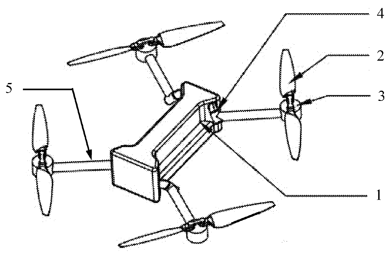
[0076] as shown in FIGS. 6-8, the four arms 5 are evenly distributed around the fuselage 1, and connected to the fuselage 1 through four rotating mechanisms 4; wherein the four rotating mechanisms 4 are respectively mounted at four corners at a bottom of the fuselage 1, enabling the arms 5 to rotate around the rotating mechanism 4 within a plane. Each of the arms 5 comprises the motor 3 and the foldable blades 2, wherein the motor 3 is fixedly connected to the arm 5, and the foldable blades 2 are fixedly connected to the motor 3.

[0077]The arms 5 are formed by the front arms and the rear arms. There are two front arms which are connected to a front of the fuselage 1 through the rotating mechanism 4, and the rotating mechanism 4 is placed at a front of a bottom of the fuselage 1. When being unfolded, the front arms are respectively extended to the front left and the front right of the UAV, and the foldable blades 2 are also unfolded. When being folded, the foldable blades 2 are folded...

third embodiment

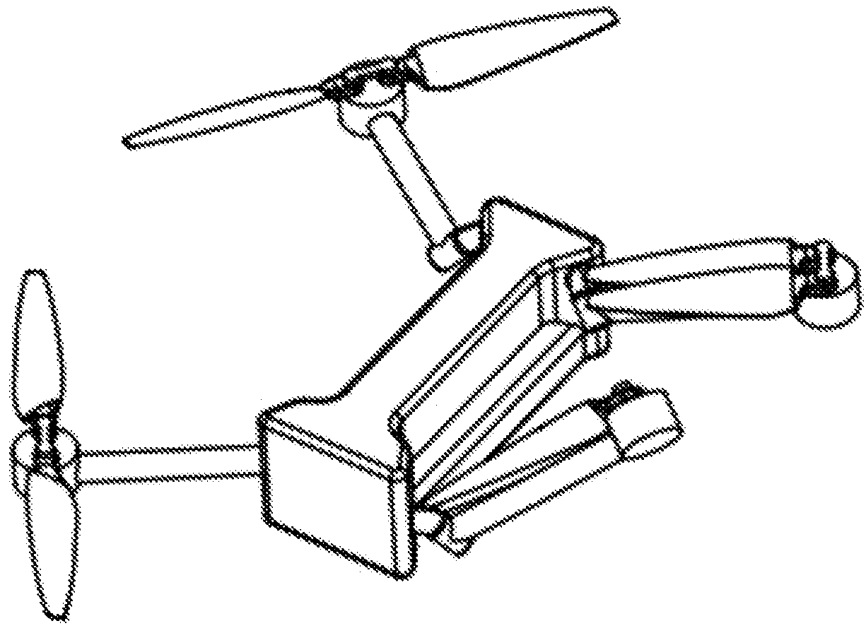
[0082] as shown in FIGS. 9-12, a first end of the arm 5 is connected to the fuselage 1 through the rotating mechanism 4, and a second end of the arm 5 is connected to the motor 3 which is connected to the foldable blades 3. The two front arms are respectively placed at front upper portions of side faces of the fuselage 1 through the rotor mechanism 4 connected to the front arms, and the two rear arms are respectively placed at rear lower portions of the side faces of the fuselage 1 through the rotor mechanism 4 connected to the rear arms. Besides, the arm 5 has a certain curvature, and cross sections of the arm 5 are different, in such a manner that after being folded, the arms 5 are staggered at both sides of the fuselage 1, so as to take full advantage of interior space of conventional straight arms with equal cross sections when being folded.

[0083]The rotating mechanism comprises a fuselage end, an arm end, and a shaft; wherein the fuselage end is connected to the arm end through...

fourth embodiment

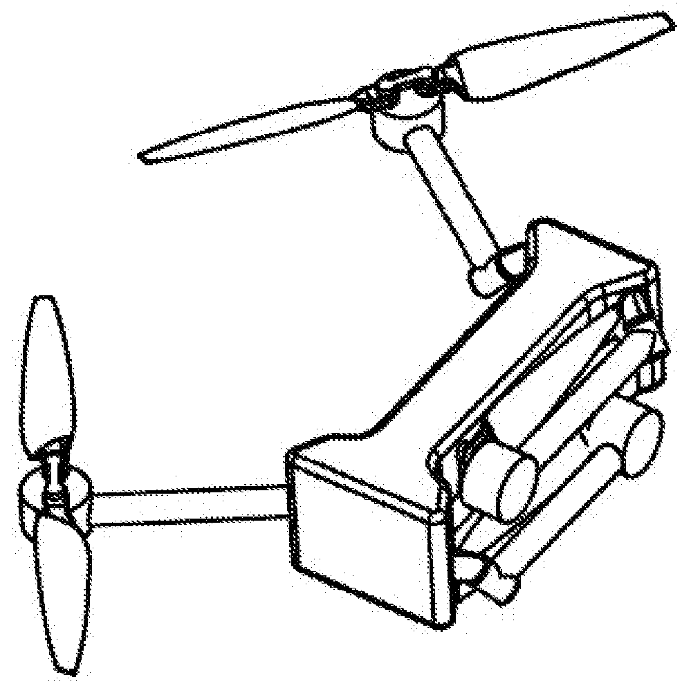
[0087] as shown in FIGS. 13-16, a first end of the arm 5 is connected to the fuselage 1 through the rotating mechanism 4, and a second end of the arm 5 is connected to the motor 3 which is connected to the foldable blades 3. The two front arms are respectively placed at front upper portions of side faces of the fuselage 1 through the rotor mechanism 4 connected to the front arms, and the two rear arms are respectively placed at rear lower portions of the side faces of the fuselage 1 through the rotor mechanism 4 connected to the rear arms. Besides, the rotating mechanism comprises a fuselage end, an arm end, and a shaft; wherein the fuselage end is connected to the arm end through the shaft. The fuselage end is a portion of the fuselage 1 which is near the arm 5, and the arm end is a portion of the arm 5 which is near the fuselage 1. The arms 5 rotate relative to the fuselage 1 when the shaft rotates, and the fuselage end of the rotating mechanism is above the arm end. The rotating ...


PUM


Abstract

A foldable multi-rotor UAV includes: a fuselage; and a plurality of arms, wherein a first end of each of the arms is connected to a side face of the fuselage through a rotating mechanism; a motor and foldable blades connected to the motor are provided on a second end of each of the arms; each of the arms rotate relatively to the fuselage through the rotating mechanism; wherein the arms comprises a front arm and a rear arm; during a folded state, the rear arm upwardly rotates towards the fuselage for folding, in such a manner that the rear arm is contained at a lower portion of the side face of the fuselage; then the front arm upwardly rotates towards the fuselage for folding, in such a manner that the front arm is contained at an upper portion of the side face of the fuselage.

Description

CROSS REFERENCE OF RELATED APPLICATION[0001]The present invention claims priority under 35 U.S.C. 119(a-d) to CN 201621396715.4, filed Dec. 19, 2016; CN 201621396871.0, filed Dec. 19, 2016; CN 201621397207.8, filed Dec. 19, 2016; CN 201621397208.2, filed Dec. 19, 2016; and CN 201621397209.7, filed Dec. 19, 2016.BACKGROUND OF THE PRESENT INVENTIONField of Invention[0002]The present invention relates to a technical field of UAV, and more particularly to a foldable multi-rotor UAV.Description of Related Arts[0003]In recent years, UAVs have been receiving more and more attention due to their simple structure, convenient handling and high safety performance. However, the conventional multi-rotor UAVs have problems such as larger size, encasing, transporting or carrying inconveniences. Conventionally, the UAV arm and the fuselage are mainly integrally formed. For the rest of the UAVs, the arm is divided into a first arm and a second arm. The first arm and the body are integrally formed, a...

Claims


Application Information

Patent Timeline
Patent Type & Authority Applications(United States)
IPC IPC(8): B64C1/30B64C39/02B64C27/50B64C27/08
CPCB64C1/30B64C39/024B64C27/50B64C27/08B64C2201/024B64C2201/108B64U10/13B64U30/20B64U80/00B64U10/10
Inventor TIAN, YUJIANG, WENYAN
Owner HAOXIANG ELECTRIC ENERGY KUNSHAN
Why Eureka
Try Eureka