Stretch flange crack prediction method, stretch flange crack prediction apparatus, computer program, and recording medium

a technology of stretching flange and crack, applied in the direction of cad techniques, instruments, design optimisation/simulation, etc., can solve the problems of high tensile stress, inability to achieve the applicable degree of accuracy during the evaluation by the existing evaluation methods, and cracks initiated in the end section of a formed component. to achieve the effect of accurate prediction

Active Publication Date: 2018-04-19
NIPPON STEEL CORP
View PDF0 Cites 8 Cited by
  • Summary
  • Abstract
  • Description
  • Claims
  • Application Information

AI Technical Summary

Benefits of technology

[0103]According to the present invention, a portion which will be fractured and a portion which wil

Problems solved by technology

However, there may be cases where cracks are initiated in an end section of a formed component during press forming depending on the material of the deformable sheet, component shape, forming conditions, and the like.
However, since cracks initiated in the end section of the formed product are significantly influenced by the properties of the end section or a strain distribution of the surrounding area of the end section, an applicable degree of accuracy cannot be achieved during the evaluation by the existing evaluation methods disclosed in Patent Documents 1 to 3.
In a case where a deformable sheet is press-formed into a three-dimensional curved shape, high ten

Method used


Image

  • Stretch flange crack prediction method, stretch flange crack prediction apparatus, computer program, and recording medium
  • Stretch flange crack prediction method, stretch flange crack prediction apparatus, computer program, and recording medium
  • Stretch flange crack prediction method, stretch flange crack prediction apparatus, computer program, and recording medium

Examples


second embodiment

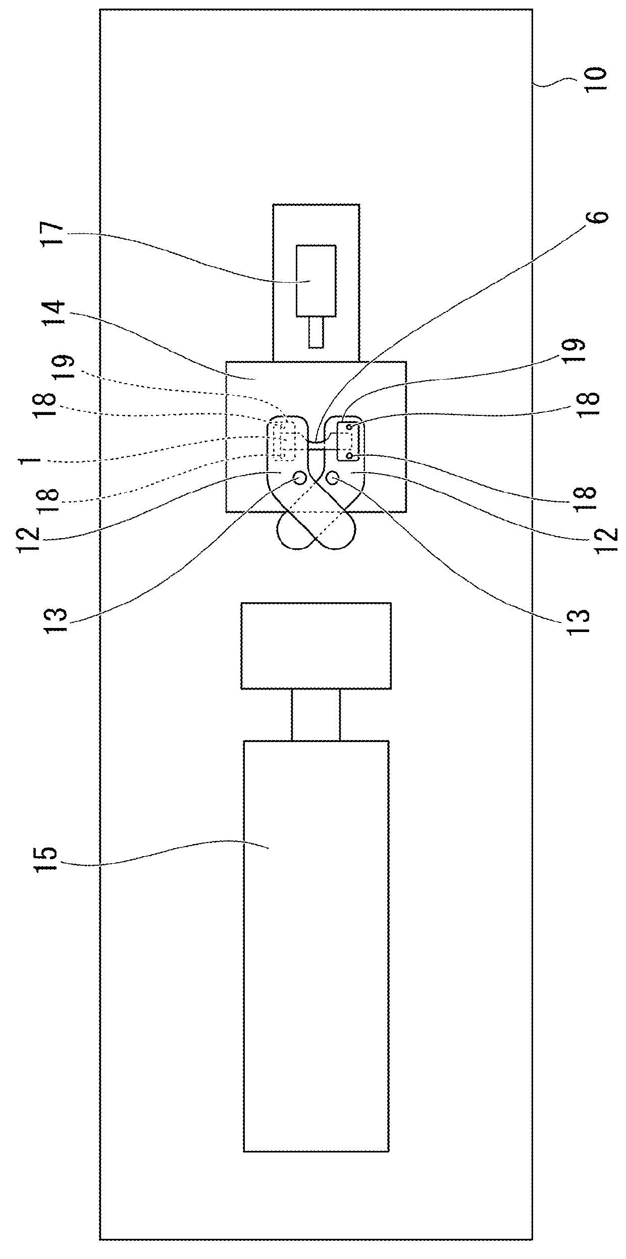
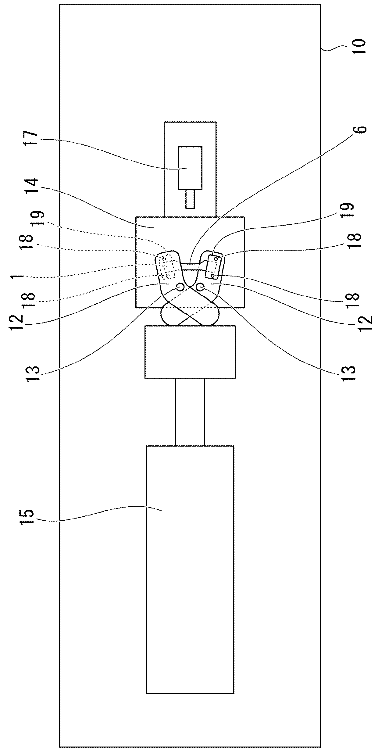
[0264]A stretch flange crack prediction apparatus 100 according to a second embodiment of the present invention executes a stretch flange crack prediction method described in the first embodiment according to an embedded computer program. As illustrated in FIG. 17, the stretch flange crack prediction apparatus 100 includes a measurement value acquisition unit 101, a CAE analysis unit 102, a fracture determination threshold acquisition unit 103, and a prediction unit 104.

[0265]The measurement value acquisition unit 101 acquires a fracture strain measurement value, a normal strain gradient measurement value, and a circumferential strain gradient measurement value, for each of a plurality of sheet-shaped test pieces, under an experimental measurement environment with a predetermined gauge length and a predetermined gradient evaluation length.

[0266]The CAE analysis unit 102 acquires, on the basis of forming data regarding a flange end section obtained through numerical analysis by a fin...

example

[0284]Next, an example of the present invention will be described. A condition of the example is a conditional example employed to confirm the applicability and effects of the present invention, and is not limited to the conditional example. The present invention can employ various conditions as long as the object of the present invention can be accomplished without departing from the gist of the present invention.

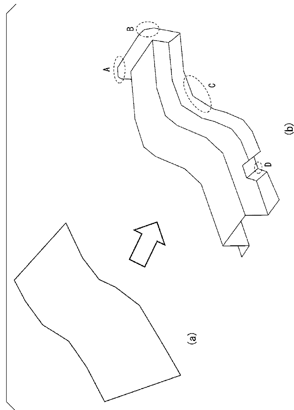
[0285]Prediction of flange cracks in a case where a saddle-shaped molded product having a shape illustrated in FIG. 19 is formed by using a cold rolled steel sheet having a sheet thickness of 1.6 mm in a tensile strength grade of 590 MPa as a black material was performed. A flange section of the saddle-shaped molded product has a height of H=20 mm and a curvature of R−1=0.033.

(Measurement Value Acquisition)

[0286]By performing punching on a cold rolled steel sheet having a sheet thickness of 1.6 mm in a tensile strength grade of 590 MPa, sheet-shaped test pieces of six type...


PUM

PropertyMeasurementUnit
Fracture strainaaaaaaaaaa
Sizeaaaaaaaaaa
Deformation enthalpyaaaaaaaaaa

Abstract

A stretch flange crack prediction method of predicting initiation of stretch flange cracks that occurs in a flange end section during stretch flange forming of a deformable sheet, includes: a measurement value acquisition process of acquiring, for each of a plurality of sheet-shaped test pieces, a fracture strain measurement value, a normal strain gradient measurement value, and a circumferential strain gradient measurement value; a CAE analysis process of acquiring a maximum major strain maximum element having a highest maximum major strain, a normal strain gradient of the maximum major strain maximum element, and a circumferential strain gradient of the maximum major strain maximum element; a fracture determination threshold acquisition process of acquiring a fracture determination threshold by converting the fracture strain measurement value; and a prediction process of predicting that stretch flange cracks will be initiated, when the maximum major strain is equal to or higher than the fracture determination threshold.

Description

TECHNICAL FIELD OF THE INVENTION[0001]The present invention relates to a stretch flange crack prediction method, a stretch flange crack prediction apparatus, a computer program, and a recording medium capable of accurately predicting initiation of stretch flange cracks that occurs in a flange end section during stretch flange forming of a deformable sheet.[0002]Priority is claimed on Japanese Patent Application No. 2014-137185, filed on Jul. 2, 2014, the content of which is incorporated herein by reference.RELATED ART[0003]Hitherto, vehicle components or other components have been manufactured by press-forming deformable sheets (for example, 270 to 1470 MPa grade high strength steel sheets). However, there may be cases where cracks are initiated in an end section of a formed component during press forming depending on the material of the deformable sheet, component shape, forming conditions, and the like.[0004]In-plane cracks initiated in a deformable sheet during drawing or forming...

Claims


Application Information

Patent Timeline
IPC IPC(8): G06F17/50B21D22/20
CPCG06F17/5018B21D22/201G06F2217/42G06F2217/16B21D22/00G06F30/23G06F2113/24G06F30/00Y02T10/82G06F2111/10
Inventor SHIRAKAMI, SATOSHIYOSHIDA, HIROSHIMIYAGI, TAKASHINITTA, JUNYOSHIDA, TOHRU
Owner NIPPON STEEL CORP
Why Eureka
Try Eureka