Automatic Generation of Test Layouts for Verifying a DRC Deck

a technology of design verification and test layout, applied in the direction of cad techniques, configuration cad, instruments, etc., can solve the problems of inability to adapt to the design of integrated circuits, the number of such layouts can increase exponentially to the point of unworkability, and the design design can be effectively verified. , to achieve the effect of increasing the yield of manufacturing the circui

Active Publication Date: 2018-04-19
APPLIED MATERIALS INC
View PDF1 Cites 9 Cited by
  • Summary
  • Abstract
  • Description
  • Claims
  • Application Information

AI Technical Summary

Benefits of technology

[0015]It will be appreciated that the present methods and system may find application in a design and production process leading ultimately to the manufacture of integrated circuits. In one application, the present disclosure provides a method for verifying a DRC deck comprising the automated generation of test layouts as described herein and verifying the DRC deck using the test layouts. In a further application, the present disclosure provides a method for verifying a circuit design comprising the verifying of

Problems solved by technology

Due to the complexity and sheer number of circuit parts in a typical integrated circuit, the DRC process is typically performed using CAD software or more specifically DRC software.
Manual generation of test layouts is limited by the imagination, expertise, and diligence of the person tasked with creating the layouts.
Unfortunately, the known method relies on error markers in an integrated circuit design which may not be adapted to cover the rules of a specific DRC deck.
It is presently recognized that wh

Method used


Image

  • Automatic Generation of Test Layouts for Verifying a DRC Deck
  • Automatic Generation of Test Layouts for Verifying a DRC Deck
  • Automatic Generation of Test Layouts for Verifying a DRC Deck

Examples


first embodiment

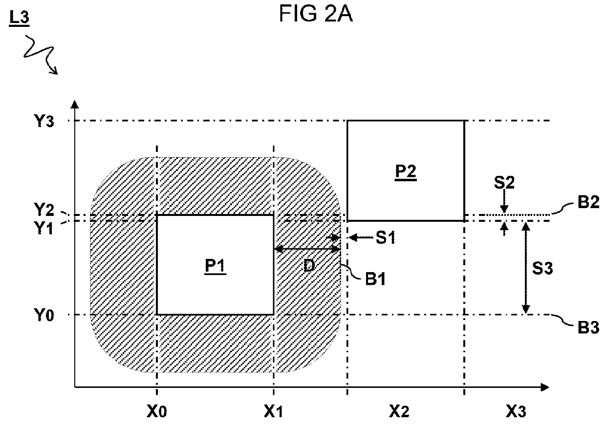
[0053]FIG. 2A schematically illustrates two polygon shapes P1 and P2 in a layout L2. The polygon shapes P1 and P2 are defined e.g. by the coordinates Xn and Yn (n=1,2,3,4) of their respective edges. Also shown in the figure is a hatched area around the first polygon shape P1 that should not be occupied by the second polygon shape P2 for reasons of manufacturability.

[0054]In one embodiment, the constraints comprise manufacturability (DRC) constraints Cm defining a minimum distances D between edges X1,X2 of the one or more polygon shapes P1,P2 for verifying compliance of the integrated circuit design with a selected manufacturing process. In one embodiment, the constraints comprise topology constraints Ct defining a sequence and / or number of edges Y0,Y1,Y2 of the one or more polygon shapes P1,P2 for preserving a relative layout of the one or more polygon shapes P1,P2. In the present embodiment, the design rule R1 comprises a Boolean combination of a manufacturability constraint Cm tha...

second embodiment

[0059]FIG. 3A schematically illustrates two polygon shapes P1 and P2 in a layout L2. The embodiment is similar to that of FIG. 2A, except that in this case the polygon shape P2 is within the minimum allowed distance D from the polygon shape P1 according to the design rule R1. Accordingly, the manufacturability constraint Cm of the design rules R1 is not satisfied and the layout constitutes a fail case. Another difference with FIG. 2A is that the polygon shape P2 is now initially closer to the boundary B3 than to boundary B2 of the topology constraints Ct.

[0060]FIG. 3B schematically illustrates a second test layout L3 derived from the layout of FIG. 3A after optimization. Similar as described with reference to FIG. 2B, slack variables S1,S2,S3 can be derived from the constraints of the design rule R1. However, in this case because the first constraint Cm is not satisfied, the slack variable S1 is added to the right hand side of the equation. Alternatively, the slack variable may be a...

third embodiment

[0061]FIG. 4A schematically illustrates two polygon shapes P1 and P2 in a layout L2. It will be noted that because the second polygon shape P2 is no longer next to the first polygon shape P1, a different design rule R1′ (or a sub rule of the same design criterion) may come into play. In this case the design rule R1′ is somewhat more complicated due to the curved boundary B1 indicating the minimum distance D between the polygon shapes. It is demonstrated by this example that the constraints may comprise non-linear terms of one or more multiple polygon parameters. In one embodiment, the minimizing of the slack is performed by a linear or nonlinear optimizer.

[0062]In one embodiment, the slack related to manufacturability constraint Cm (e.g. distance checks in the rule at test) is minimized before slack related to topology constraints Ct. Furthermore, if two slack expressions have equal value in the random start layout, it is preferred to give the expression with the smallest absolute v...


PUM


Abstract

A computer-implemented method for automated generation of test layouts for verifying a DRC deck. The method comprises receiving a first layout (L1) comprising one or more polygon shapes (P1) defined by a plurality of polygon parameters (W1,H1). Design rules (R1,R2) are received comprising inequality constraints (C) on the polygon parameters (W1,H1). A second lay-out (L2) is calculated by applying a random change (ΔW12) of value to at least one of the polygon parameters (W1) of the first layout (L1). A third layout (L3) is calculated by varying values of the polygon parameters (W1,H1) of the second layout (L2) until a respective slack (S1,S2) of the polygon parameters (W1,H1) with respect to one or more of the parameter boundaries (B1,B2) defined by the constraints is minimized The third layout (L3) may be stored as candidate test layout.

Description

TECHNICAL FIELD AND BACKGROUND[0001]The present disclosure relates to computer-aided testing for design verification of integrated circuits, and more particular a method for automated generation of test layouts for verification of design rule checking decks.[0002]Design Rule Checking (DRC) is an area of Electronic Design Automation (EDA) that is used to determine whether the layout design of an integrated circuit satisfies a series of recommended parameters called design rules. Due to the complexity and sheer number of circuit parts in a typical integrated circuit, the DRC process is typically performed using CAD software or more specifically DRC software. An example of DRC software is Calibre® by Mentor Graphics®. Typically, the design rules are specific to a particular manufacturing process and may specify for example certain geometric and connectivity restrictions to ensure sufficient margins to account for variability in the manufacturing processes. A set of design rules for a p...

Claims


Application Information

Patent Timeline
IPC IPC(8): G06F17/50G01R31/317
CPCG06F17/5081G01R31/31704G06F2217/06G06F2217/02G06F11/263G06F11/3684G06F30/398G06F2111/04G06F2111/20
Inventor BERKENS, MARTINUS MARIA
Owner APPLIED MATERIALS INC
Why Eureka
Try Eureka