

Bezel assembly for use with an automated transaction device
a technology for automating transaction devices and bezels, which is applied in the field of bezels for bill validators, can solve the problems that many conventional transactional devices cannot receive mobile payments, and many conventional transactional devices cannot allow data to be received from the consumer's phone or input by the consumer, so as to achieve more security in the transaction
Active Publication Date: 2018-04-19
JCM AMERICAN CORP
View PDF0 Cites 7 Cited by
- Summary
- Abstract
- Description
- Claims
- Application Information
AI Technical Summary
Benefits of technology
The present invention relates to a bezel assembly for data reception. The assembly includes a biological sensor, such as a fingerprint reader or finger vein reader, and a sending module for forwarding the biometric information to a bill validator. The bill validator receives the biometric information and sends it to a transactional computer for identifying the user based on the biometric information and the ID signal. This helps to enhance security in transactions. The biological sensor is located in the hollow tongue or protrusion of the receiving device, and can be accessed through a fingerprint or finger vein pattern. The invention provides an improved method to verify the user's identity and prevent unauthorized access to data.
Problems solved by technology
Currently, though a consumer might find it convenient to use his or her mobile device for wireless mobile payments as an alternative to paper notes at a transactional device (such as a gaming machine, vending machine, ATM, transactional kiosk, customer self-service device, payment terminals, points-of-sale, or the like), most transactional devices that are being produced or that are already deployed in the field are not operable to allow data to be received from the consumer's phone or to be input by the consumer.
For example, many conventional transactional devices cannot receive a mobile payment facilitated by the phone's wireless communication capability or display capability (such as displaying an encoded barcode, matrix code, or the like).
Nor are many conventional transactional devices able to allow the consumer to input data.
Though it would be advantageous to upgrade legacy transactional devices to enable them to receive data input by the consumer or from the consumer's phone, adding this additional data reception functionality into these legacy transactional devices may require expensive or complex modifications to the device.
Even in newly manufactured transactional device cabinets, where a wireless receiver may be placed in any of a variety of places in the cabinet inside, the thickness and material of the exterior of the cabinet is likely to reduce the efficiency of the wireless transmission.
However, this solution makes it harder for the consumer to determine how or where to initiate a mobile wireless transaction or how or where to input additional data.
Current attempts to incorporate wireless communication functionality into a bezel have produced a large and cumbersome bezel that is not suitable for use in the extremely limited, defined space of many transactional devices.
Also, existing bezels have placed some types of wireless communication devices (such as chip & PIN card readers) in a vertical wall, which does not intuitively indicate to the consumer the location to which the mobile phone should be touched (or brought into close proximity), does not assist the consumer in positioning the mobile phone in the proper location, does not provide optimum wireless connectivity, and does not prevent the consumer from attempting to make both a paper note transaction and a wireless transaction simultaneously (which is likely to cause an error in the transactions attempted as the transactional software is not designed to accept simultaneous transactions).
Though some wireless communication bezels are currently available, they are too large and bulky to fit in this limited space and do not meet this limitation.
The current configurations of bill validators are limited to accepting only printed notes.
This configuration is adapted for current paper technology, but introduces limitations when considering upcoming e-wallets and other technological advances on the horizon, wherein the data representing financial value submissions (payments, tokens, and the like) can be presented on, displayed on, or otherwise provided by non-insertable media having any of a variety of form factors, including images displayed on electronic wallets, tablets, personal data assistants, smart phones, and the like, and including electronic wireless financial transfers, and the like.
Method used
View moreImage
Smart ImageViewing Examples


Examples
fourth embodiment
[0070]2. a manual input assembly (manual entry bezel assembly for data reception 300 of the fourth embodiment is shown in FIG. 15);
fifth embodiment
[0071]3. a biological sensor (biological sensor 400 of the fifth embodiment is shown in FIG. 16); and
sixth embodiment
[0072]4. an image recognition assembly (image recognition bezel assembly for data reception 500 of the sixth embodiment is shown in FIGS. 17-22).
Login to View More PUM
 Abstract
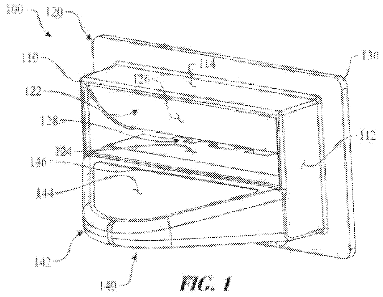
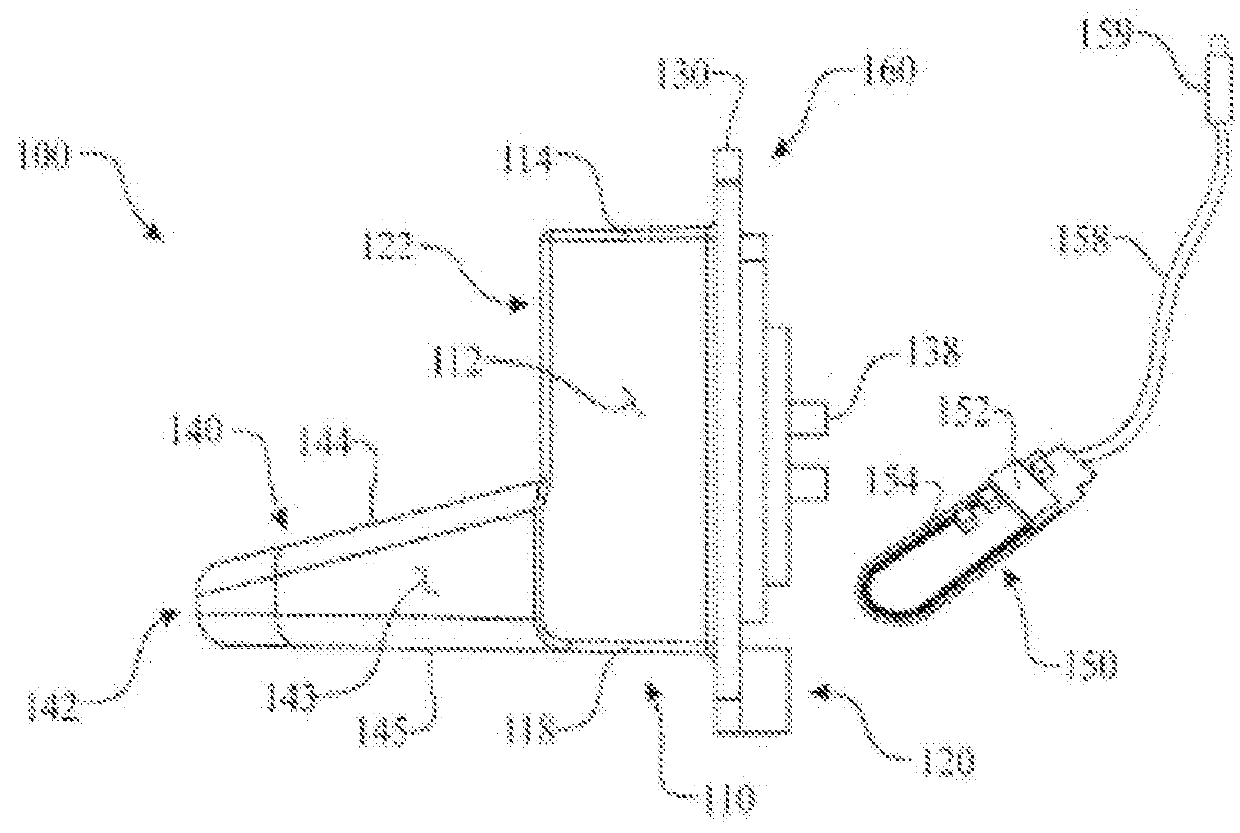
A bezel assembly for data reception is provided for use in a transactional device that comprises a door attached to open and close. The bezel assembly comprises: a casing secured to the door, an interior insertion / dispensing slot formed in the casing, a hollow tongue or protrusion forward-extending from the casing to define a bottom surface of the interior insertion / dispensing slot, and a wireless communication module arranged in the hollow tongue or protrusion for communication with a built-in NFC chip in an identification card when put in the interior insertion / dispensing slot to identify a user of the identification card.
Description
CROSS-REFERENCE TO RELATED APPLICATIONS[0001]This is the U.S. Continuation-In-Part Application of U.S. patent application Ser. No. 15 / 284,472 filed on Oct. 3, 2016 which claims the benefit of U.S. patent application Ser. No. 14 / 614,180 filed on Feb. 4, 2015 now matured into U.S. Pat. No. 9,483,894 which is a Continuation of application Ser. No. 14 / 033,483 filed on Sep. 22, 2013 now U.S. Pat. No. 8,978,868 which claims the benefit of U.S. Provisional Patent Application Ser. No. 61 / 708,632 filed on Oct. 1, 2012.FIELD OF INVENTION[0002]This invention relates generally to a bezel for a bill validator mounted in a transactional device that is configured to receive data as well as providing an insertion slot for a bill validator.BACKGROUND OF THE INVENTION[0003]The insertion slot of a bezel of a bill validator provides a conspicuous location for consumers to input notes, such as currency, paper tickets, scrip, vouchers, bills, and other similar documents. Use of bill validators has provid...
Claims
Login to View More Application Information
Patent Timeline
 Patent Type & AuthorityApplications(United States)
IPC IPC(8): G07D11/00G07F19/00
CPCG07F19/205G07F19/20Y10S902/06G07D11/0018G07D11/0036G07D11/0051Y10S902/08
InventorKAMIHIGASHI, KOICHIROJOHNSON, STEVERIVERA, OMAR JORGETOTH, SCOTT A.PETERSEN, DANIELMOHRHARDT, DOMINIC
OwnerJCM AMERICAN CORP