Portable breathing machine

a breathing machine and portability technology, applied in the field of breathing machines, can solve problems such as damage to the main body, achieve the effects of reducing the temperature of the fan, facilitating assembly and maintenance, and increasing the noise reduction degr

Active Publication Date: 2018-04-26
HUNAN MICOME ZHONGJIN MEDICAL SCI & TECH DEV CO LTD
View PDF0 Cites 9 Cited by
  • Summary
  • Abstract
  • Description
  • Claims
  • Application Information

AI Technical Summary

Benefits of technology

[0040]The present invention solves the problem of noise reduction from the air channel structure combined with the fan noise reduction device through following technical solutions.
[0041]1) The S-shaped air channel is arranged at the fan air inlet; through at least three sinuous sections, the wind howling sound generated by the friction between the blades of the fan and air is effectively avoided.
[0042]2) The S-shaped air channel and the fan air inlet channel are integrated together and sealed in the fan box, so that noise is also controlled in the fan box, which further increases the noise reduction degree and facilitates assembling and maintaining. Meanwhile, through the enclosed S-shaped air channel, the external gas firstly passes through the upper part of the enclosed cavity and the descends to the fan air inlet at the bottom part of the fan; when passing through the enclosed cavity, the external gas brings the heat generated by the fan to the fan air outlet, thereby decreasing a temperature of the fan.
[0043]3) The fan air outlet is connected with the flexible connection tube, so that gas is transmitted to the patients freely and the noise generated by the collision between the fan air outlet and the external air channel due to the shock of the fan is avoided.
[0044]The abov

Problems solved by technology

The existing problems in prior art are that a conventional breathing machine has a large noise, and water in a water box

Method used


Image

  • Portable breathing machine
  • Portable breathing machine
  • Portable breathing machine

Examples


Embodiment Construction

[0088]The following preferred embodiment is for illustrating the present invention, but not for limiting the scope of the present invention.

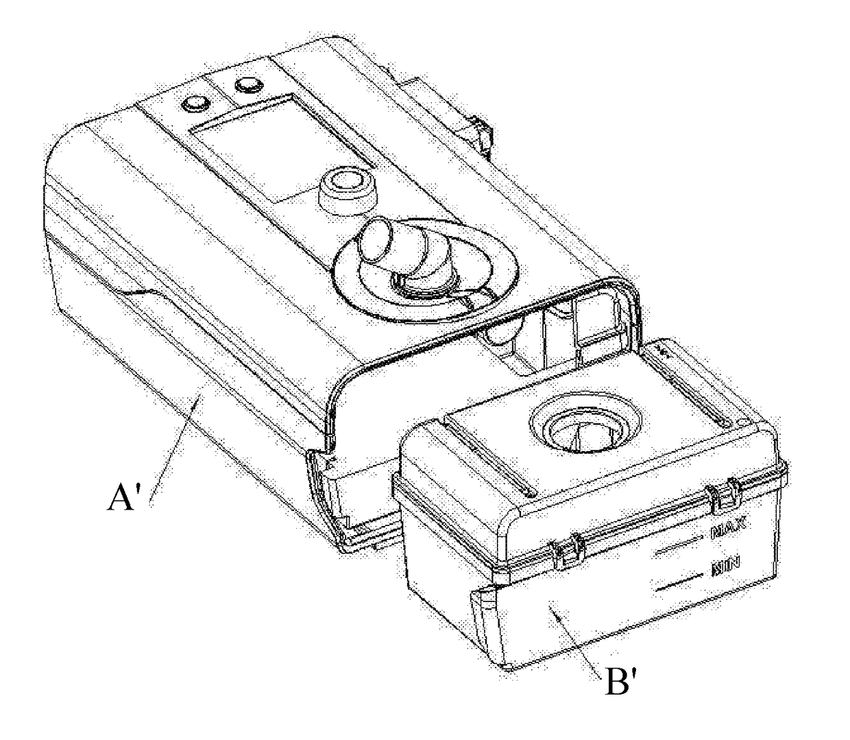
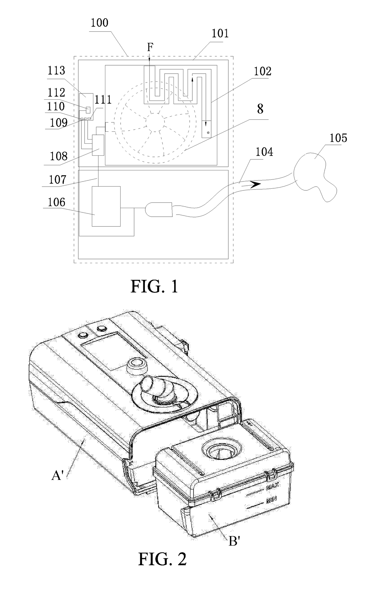
[0089]As shown in FIG. 1, according to a preferred embodiment of the present invention, a low-noise breathing machine comprises a body case 100, wherein: an air inlet of the breathing machine is arranged at the body case 100; a fan box 101, a fan noise reduction device 102, a cut-off device 108, a heating and humidifying device 106 and a control device 113 are arranged in the body case 100; a fan 8 is arranged in the fan box 101 through the fan noise reduction device 102; an air outlet of the fan box 101 is connected with an internal breathing tube 107; the cut-off device 108 is arranged on the internal breathing tube 107; a flow sensor109, a pressure sensor 110 and a flow velocity sensor 111 are arranged in the cut-off device 108; the flow sensor 109, the pressure sensor 110 and the flow velocity sensor 111 are all connected with the control de...


PUM


Abstract

A portable breathing machine includes a body case (100), wherein: a fan box (101), a cut-off device (108) and a control device (113) are arranged in the body case (100); a fan (8) is arranged in the fan box (101) through a fan noise reduction device (102); an air outlet of the fan box (101) is connected with an internal breathing tube (107); the cut-off device (108) is arranged on the internal breathing tube (107); an air outlet of the cut-off device (108) is connected with an external breathing tube (104) and a mask (105); the fan noise reduction device (102) includes a lower flexible cover (3) and an upper flexible cover (5); the lower and upper flexible covers cooperate to form an enclosed cavity for containing the fan (8). A working noise of the breathing machine is decreased to below 15 decibel.

Description

CROSS REFERENCE OF RELATED APPLICATION[0001]This is a U.S. National Stage under 35 U.S.C 371 of the International Application PCT / CN2016 / 076991, filed Mar. 22, 2016, which claims priority under 35 U.S.C. 119(a-d) to CN 201510129285.3, CN 201510129347.0 and CN 201510129278.3, all filed Mar. 24, 2015.BACKGROUND OF THE PRESENT INVENTIONField of Invention[0002]The present invention relates to a field of breathing machine, and more particularly to a portable breathing machine.Description of Related Arts[0003]The household sleep breathing machine is mainly applicable in personal home, sleep center and small clinic for patients having the apnea syndrome. The breathing machine is to pressurize the gas in the tube through the fan; and during the working process, it is inevitable for the fan to make a noise. Because the patients have the relatively low threshold tolerance of noise, the single and repeating stimulation generated by the noise leads that the patients cannot distinguish day and n...

Claims


Application Information

Patent Timeline
IPC IPC(8): A61M16/00A61B5/00
CPCA61M16/0006A61B5/4818A61M2016/0036A61M16/1045A61M16/0087A61M16/022A61B7/003A61M16/0816A61M16/16A61M2016/0027A61M2205/42A61M16/161
Inventor DAI, ZHENGDING, JINLIU, WEIXU, QINPENGHUANG, HAOXUANLI, WEILIHE, CHAOLEI, MENGHANGZENG, XIAOHUIWANG, GUANGRONG
Owner HUNAN MICOME ZHONGJIN MEDICAL SCI & TECH DEV CO LTD
Why Eureka
Try Eureka