Electric brake system

a technology of brake system and electric brake, which is applied in the direction of brake system, braking components, transportation and packaging, etc., can solve the problems of deteriorating hydraulic pressure supply device efficiency while abs control is performed, problems may occur in emergency braking operation as well as normal braking operation

Active Publication Date: 2018-04-26
HL MANDO CORP
View PDF30 Cites 11 Cited by
  • Summary
  • Abstract
  • Description
  • Claims
  • Application Information

AI Technical Summary

Benefits of technology

[0017]The electric brake system may further include a first control valve provided at the second hydraulic flow path and configured to control an oil flow therein; a second control valve provided at the third hydraulic flow path and configured to control an oil flow therein; and a third control valve provided at the fifth hydraulic flow path and configured to control an oil flow therein.
[0018]The first and second control valves may each be provided with a check valve configured to allow oil to flow in a direction from the hydraulic pressure supply device to the wheel cylinders and block oil from flowing in a reverse direction, and the third control valve may be provided with a solenoid valve configured to control a bidirectional oil flow between the hydraulic pressure supply device and the wheel cylinders.
[0019]The electric brake system may further include a first dump flow path communicating with the first pressure chamber and connected to the second reservoir chamber; a second dump flow path communicating with the second pressure chamber and connected to the second reservoir chamber; a first dump valve provided with a check valve which is provided at the first dump flow path, is configured to control the oil flow therein, and allows the oil to flow in the direction from the second reservoir chamber to the first pressure chamber, and blocks the oil from flowing in the opposite direction; a second dump valve provided with a check valve which is provided at the second dump flow path, is configured to control the oil flow therein, and allows the oil to flow in the direction from the second reservoir chamber to the second pressure chamber, and blocks the oil from flowing in the opposite direction; and a third dump valve provided at a bypass flow path connecting an upstream side of the second dump valve to a downstream side thereof at the second dump flow path, and provided with a solenoid valve configured to bidirectionally control an oil flow between the reservoir and the second pressure chamber.
[0020]The electric brake system...

Problems solved by technology

However, in the above-described case, efficiency of the hydraulic pressure supply device may be deteriorated while ABS control is performed.
However, in the case in which the master cylinder and the hydraul...

Method used


Image

  • Electric brake system
  • Electric brake system
  • Electric brake system

Examples


Embodiment Construction

[0027]Hereinafter, embodiments of the present disclosure will be described in detail with reference to the accompanying drawings. The embodiments, which will be described below, are provided to fully convey the spirit of the present disclosure to those skilled in the art. The present disclosure is not limited to the embodiments disclosed herein, and may be implemented in other forms. In the drawings, some portions not related to the description will be omitted and not shown to clearly describe the present disclosure, and also a size of a component may be somewhat exaggerated to facilitate understanding.

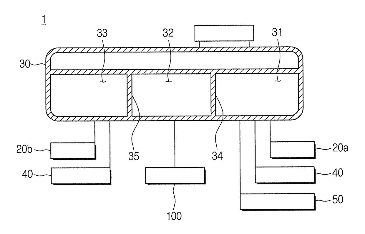
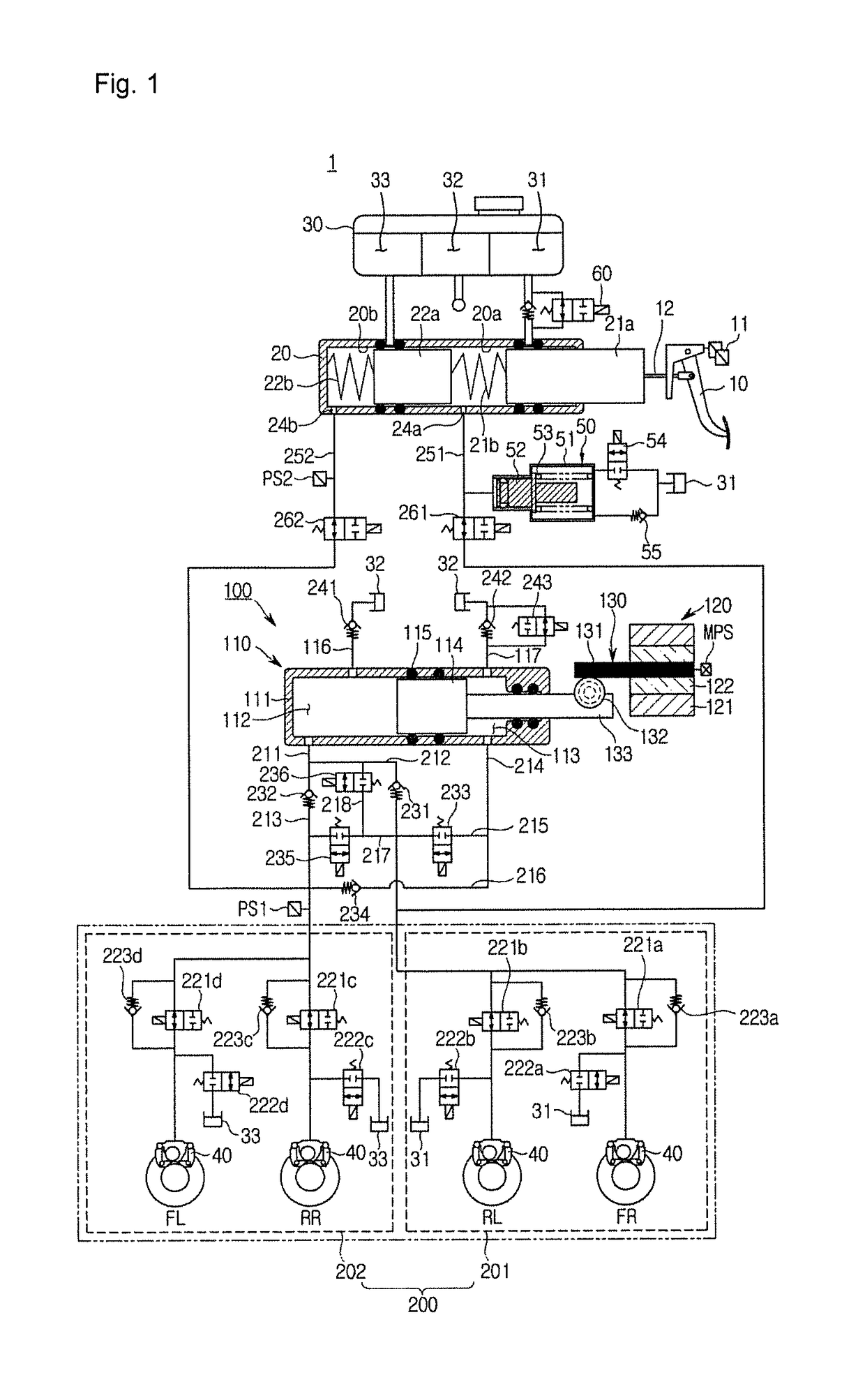
[0028]FIG. 1 is a hydraulic pressure circuit diagram illustrating a non-braking state of an electric brake system 1 according to an embodiment of the present disclosure.

[0029]Referring to FIG. 1, the electric brake system 1 is generally configured with a master cylinder 20 configured to generate a hydraulic pressure, a reservoir 30 coupled to an upper part of the master cylinder 20 to...


PUM


Abstract

Disclosed is an electric brake system. The electric brake system includes a reservoir configured to store oil, a master cylinder connected to the reservoir, provided with first and second master chambers and first and second pistons respectively provided at the first and second master chambers, and configured to discharge oil according to pedal effort of a brake pedal; a hydraulic pressure supply device operated to generate a hydraulic pressure by an electrical signal output in response to displacement of the brake pedal; and a hydraulic pressure control unit configured to deliver the hydraulic pressure discharged from the hydraulic pressure supply device to a wheel cylinder provided at each of wheels, wherein the reservoir includes a first reservoir chamber connected to the master cylinder and configured to supply the oil thereto, and a second reservoir chamber connected to the hydraulic pressure supply device, configured to supply the oil thereto and provided to be separated from the first reservoir chamber.

Description

[0001]This application claims the benefit of Korean Patent Application No. 2016-0140052, filed on Oct. 16, 2016 in the Korean Intellectual Property Office, the disclosure of which is incorporated herein by reference.BACKGROUND1. Field[0002]Embodiments of the present disclosure relate to an electric brake system, and more particularly, to an electric brake system configured to generate a braking force using an electrical signal.2. Description of the Related Art[0003]Generally, a reservoir is a tank for storing brake fluid or hydraulic oil of a power steering device.[0004]Specifically, a brake reservoir tank in which brake fluid is stored is disposed above a master cylinder to store brake fluid supplied thereto to the master cylinder, and is configured to detect a residual amount of the brake fluid and operate a warning lamp to inform a driver of the detected residual amount.[0005]A brake system, which is configured such that oil is discharged from a master cylinder to be directly del...

Claims


Application Information

Patent Timeline
IPC IPC(8): B60T13/74B60T13/68B60T8/17B60T13/14
CPCB60T13/745B60T13/686B60T8/17B60T13/142B60T8/4081B60T13/662B60T2270/404B60T11/26B60T11/22B60T17/223B60T17/06
Inventor KIM, JONG-WOOK
Owner HL MANDO CORP
Why Eureka
Try Eureka