Travel control apparatus and travel control method

a technology of control apparatus and control method, which is applied in the direction of vehicle position/course/altitude control, process and machine control, instruments, etc., can solve the problems of vehicle being placed in an unstable traveling state, vehicle to be not thoroughly manipulated, and difficulty in switching to the control for automatic evacuation

Active Publication Date: 2018-04-26
DENSO CORP
View PDF2 Cites 96 Cited by
  • Summary
  • Abstract
  • Description
  • Claims
  • Application Information

AI Technical Summary

Benefits of technology

[0009]According to the above aspects of the present disclosure, the vehicle can steadily travel as driving assistance control is exercised to prevent the deviation of the vehicle from a traveling lane even during the interval between the detection of driver abnormality and the determination of driving difficulty. Consequently, when the driver is having difficulty in driving the vehicle, the travel control apparatus can properly switch to automatic evacuation control for automatically stopping the vehicle at a place where the vehicle may stop.

Problems solved by technology

Such an interval may pose the vehicle to be not thoroughly manipulated by the driver having truly difficulty in driving the vehicle; thereby the vehicle may be placed in an unstable traveling state before the start of automatic evacuation.
This may cause difficulty in switching to the control for automatic evacuation.

Method used


Image

  • Travel control apparatus and travel control method
  • Travel control apparatus and travel control method
  • Travel control apparatus and travel control method

Examples


first embodiment

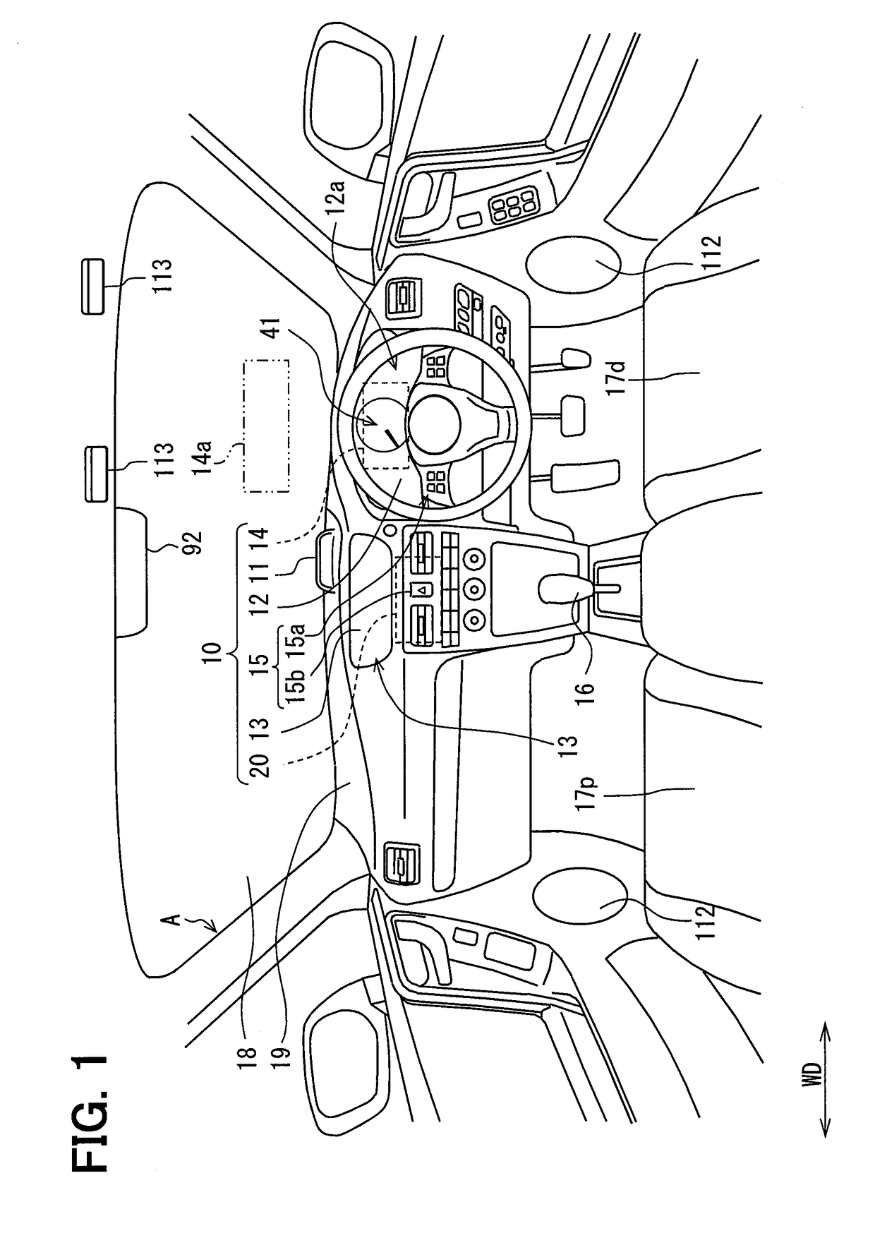
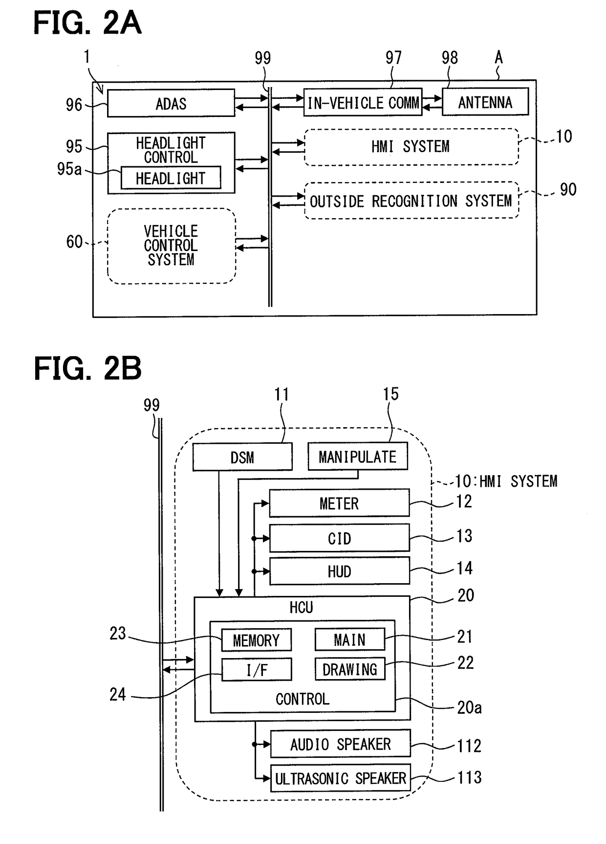
[0045]As in FIGS. 1 and 2A to 2D, a vehicle control ECU 70 according to a first embodiment of the present disclosure is an electronic apparatus mounted in a vehicle A. The vehicle A is referred to also as a subject vehicle. The vehicle control ECU 70 is one of a plurality of nodes in an in-vehicle network 1 mounted in the vehicle A. The in-vehicle network 1 includes an ADAS locator 96, an in-vehicle communicator 97, a headlight control apparatus 95, an outside recognition system 90, an HMI system 10, and a vehicle control system 60. These elements are connected to a communication bus 99 and capable of establishing communication to exchange information with each other. The word “information” is used not only as an uncountable noun but also as a countable noun. A plurality of informations are equivalent to a plurality of items of information.

[0046]The ADAS (Advanced Driver Assistance Systems) locator 96 includes a GNSS (Global Navigation Satellite System) receiver, a gyro sensor or ot...

second embodiment

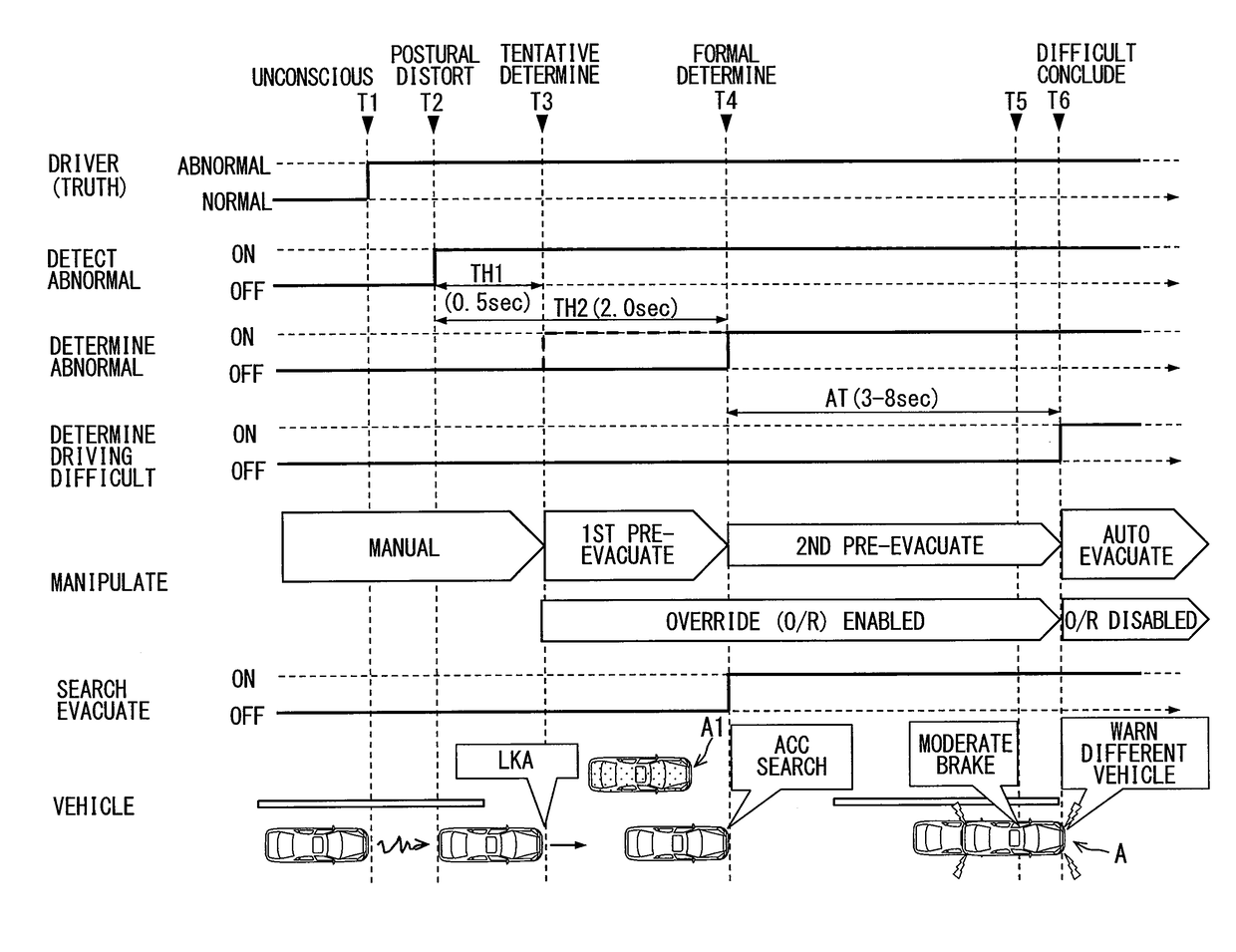
[0158]A second embodiment of the present disclosure is illustrated in FIGS. 22 to 24. The second embodiment is obtained by modifying the first embodiment. If the driver does not respond to a notification of postural distortion that is issued based on a tentative determination, the second embodiment activates the LKA as a driving assistance function. A pre-evacuation control process according to the second embodiment will be described below based on FIGS. 22 and 23 while referring to FIGS. 1 to 3. A process performed before tentative determination (before T23) and a process performed after formal determination (after T25) are substantially the same as those in the first embodiment and will not be redundantly described.

[0159]When an abnormal state is tentatively determined to exist (T23), the postural distortion icon 45 (see FIG. 10) is projected onto the projection area 14a based on such a tentative determination in order to notify the driver that an abnormality, such as a postural d...

third embodiment

[0164]A third embodiment of the present disclosure is illustrated in FIGS. 25 to 28. The third embodiment is obtained by modifying the first embodiment. The vehicle exterior notification section 89 (see FIG. 3) according to the third embodiment establishes vehicle-to-vehicle communication to distribute a predictive warning (hereinafter referred to as “switching notice distribution”) before distributing a warning based on the initiation of automatic evacuation control (hereinafter referred to as “conclusive warning distribution”). Switching notice distribution notifies a different vehicle A1 of the possibility of the driver of the vehicle A having difficulty in driving. Switching notice distribution is initiated together with the second notification (see T4 of FIG. 25 and S308 of FIG. 28) when the driver does not respond to the first notification and is formally determined to be abnormal. Based on the determination of the driving difficulty state, switching notice distribution contin...


PUM


Abstract

A travel control apparatus includes: an abnormality information acquisition section that acquires information indicating that an abnormality of a driver of a vehicle is detected; a status determination section that makes a determination that the driver is in a driving difficulty state, when the abnormality of the driver is detected continuously; and an evacuation control section that initiates an automatic evacuation control stopping automatically the vehicle when the status determination section makes a determination that the driver is in the driving difficulty state. The travel control apparatus further includes an assistance control section that initiates a driving assistance control during an interval from when the abnormality is detected to when the driving difficulty state is determined; the driving assistance control includes at least activating a lane departure prevention function of the vehicle.

Description

CROSS REFERENCE TO RELATED APPLICATION[0001]The present application is based on Japanese Patent Application No. 2015-77083 filed on Apr. 3, 2015, and Japanese Patent Application No. 2016-19920 filed on Feb. 4, 2016, the disclosures of which are incorporated herein by reference.TECHNICAL FIELD[0002]The present disclosure relates to a travel control apparatus and a travel control method that control the travel of a vehicle.BACKGROUND ART[0003]When the driver of a vehicle has difficulty in driving the vehicle, a conventionally known travel control apparatus described, for example, in Patent Literature 1 automatically stops a vehicle instead of the driver. Upon detecting an abnormality of the driver, the travel control apparatus performs an intention confirmation process to ask the driver whether automatic evacuation is required. When the result of the intention confirmation process indicates that the driver has difficulty in driving the vehicle, the travel control apparatus begins cont...

Claims


Application Information

Patent Timeline
Patent Type & Authority Applications(United States)
IPC IPC(8): B60W50/12B60W30/12B60W30/16B60W40/08B60W50/14B60Q1/46G05D1/00B60T7/14
CPCB60W50/12B60W30/12B60W30/16B60W40/08B60W50/14B60Q1/46G05D1/0061B60T7/14B60W2040/0818B60K28/06B60W30/143B60W2050/0096B60Y2302/05G08G1/167B60W2540/215B60W2540/225B60W2540/223B60W2540/229B60W2540/10B60W2710/202B60W50/082B60W2420/52B60W2420/403
Inventor TAMAGAKI, MITSUOTANAKA, HIROAKISHIMONOMOTO, IFUSHIKAMIYA, AKIRAMORI, TAKUYAFUJISAWA, YUKIKOTANI, AYAKO
Owner DENSO CORP
Why Eureka
Try Eureka