Unlock instant, AI-driven research and patent intelligence for your innovation.

Catalytic Converter and Method of Controlling Exhaust Emission

a catalytic converter and exhaust emission technology, applied in the direction of electrical control, physical/chemical process catalysts, separation processes, etc., can solve the problems of discharge, harmful substances, problematic layout, etc., to reduce the content of entire noble metals, improve the emission reduction performance, and reduce the time needed

Active Publication Date: 2018-04-26
HYUNDAI MOTOR CO LTD
View PDF4 Cites 0 Cited by
  • Summary
  • Abstract
  • Description
  • Claims
  • Application Information

AI Technical Summary

Benefits of technology

This patent improves the performance of catalytic converters by reducing the time needed to reach a catalyst light-off temperature and reducing the amount of expensive noble metals needed for the catalyst. The method also controls exhaust gas emissions using the improved catalytic converter.

Problems solved by technology

When a vehicle engine is started at room temperature or below, harmful substances, such as THC, CO, NOx and the like, are discharged before the catalyst reaches the light-off temperature (“LOT”) because the exhaust gas cannot processed and purified by the catalyst.
Existing approaches, however, lead to problematic layouts and increased catalyst cost.
Generally, when a gasoline engine is operated in a high speed and a high load area, there is a risk that the temperature of exhaust gas becomes high and the hot exhaust gas flows into the catalyst, thereby damaging the catalyst.
By controlling the richness of the air-fuel ratio in a high-speed and high-load condition, exhaust gas rich in hydrocarbons is introduced into the catalyst, which degrades the emissions reduction performance of the catalyst, as compared to the catalyst performance under the theoretical air-fuel ratio condition.
This conventional emissions reduction system is inferior in terms of cost and weight because it requires both the WCC and the UCC.
As a result, the emissions reduction performance of the catalytic converter is reduced, resulting in excessive emissions discharge.
In order to increase the efficiency of the emissions reduction performance, noble metal or the like is used as the catalyst, which increases the cost.
In particular, for example, the T-GDI catalyst device requires an excessively long time to reach the catalyst light-off temperature, and noble metal that is coated on the substrate of the catalyst is rapidly consumed due to the temperature decline of the catalyst.

Method used

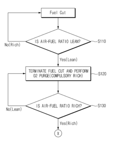

Image

  • Catalytic Converter and Method of Controlling Exhaust Emission
  • Catalytic Converter and Method of Controlling Exhaust Emission
  • Catalytic Converter and Method of Controlling Exhaust Emission

Examples


Embodiment Construction

[0026]Example embodiments of the present disclosure are described with reference to the accompanying drawings in detail. The same reference numbers are used throughout the drawings to refer to the same or like parts. Detailed descriptions of well-known functions and structures incorporated herein may be omitted to avoid obscuring the subject matter of the present disclosure.

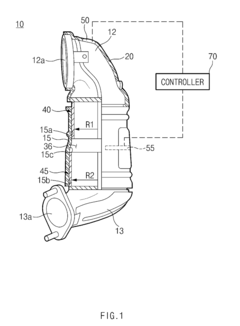
[0027]Referring to FIGS. 1 to 4, a catalytic converter 10 according to an embodiment of the present disclosure may include a housing 15 and two or more catalyst substrates 40 and 45 provided inside housing 15.

[0028]FIG. 1 is a cross-sectional view illustrating a part of the catalyst substrates 40 and provided in the housing 15. As shown in FIG. 1, housing 15 may include accommodating sections 15a and 15b, each capable of individually accommodating a catalyst substrate. Each of accommodating sections 15a and 15b may be formed to fit a corresponding outer diameter of catalyst substrates 40 and 45.

[0029]An inlet cap...


PUM

PropertyMeasurementUnit
volumeaaaaaaaaaa
volumeaaaaaaaaaa
lengthaaaaaaaaaa

Abstract

The present disclosure relates to an improved catalytic converter capable of significantly reducing emissions by reducing the activation time of a catalytic device thereby improving emissions reduction performance, and an exhaust emission emissions reduction control method using the improved catalytic converter. The improved catalytic converter includes: a housing and two or more catalyst substrates disposed inside the housing, wherein the two or more catalyst substrates are separated inside the housing along a longitudinal direction, and the two or more catalyst substrates have a different diameter and a different volume.

Description

CROSS-REFERENCE TO RELATED APPLICATION[0001]This application claims the benefit of and priority to Korean Patent Application No. 10-2016-0140402, filed on Oct. 26, 2016 in the Korean Intellectual Property Office, the disclosure of which is incorporated herein in its entirety by reference.BACKGROUNDTechnical Field[0002]The present disclosure relates to a catalytic converter, and more particularly, to a catalytic converter capable of significantly reducing emission by reducing an activation time of a catalytic device and improving emissions reduction performance, and an exhaust emission emissions reduction control method using the same.Description of the Related Art[0003]The regulations on discharge of total hydrocarbons (“THC”), carbon monoxide (“CO”), and nitrogen oxide (“NOx”) become more stringent as the environmental regulation for vehicle exhaust gas transitions to the Super Ultra Low Emission Vehicle (“SULEV”) standard from Ultra Low Emission Vehicle II (“ULEV II”). For example...

Claims


Application Information

Patent Timeline
Patent Type & Authority Applications(United States)
IPC IPC(8): F01N3/20F01N3/28F01N11/00F02D41/14B01D53/94B01J23/40B01J35/00
CPCF01N3/20B01D2255/1028F01N3/2882F01N11/007F02D41/1454B01D53/9431B01D53/9413B01J23/40B01J35/0006F01N2370/02F01N2510/0682B01D2255/1021B01D2255/1023B01D2255/1025B01D2255/1026B01D2255/102F01N3/2803B01D53/9445B01D53/9495F01N3/101F01N3/105F01N3/2006F01N3/28F01N2340/02F01N2430/06F01N2450/00F01N2510/06F01N2560/025F01N2900/1402F01N2900/1624F01N13/0097F01N13/0093F02D41/123F02D41/0295F02D41/126B01J37/0244Y02T10/12B01J35/19
Inventor JANG, CHUN SOON
Owner HYUNDAI MOTOR CO LTD