

Soundproof structure
a soundproof structure and soundproofing technology, applied in the direction of synthetic resin layered products, building components, constructions, etc., can solve the problems of poor heat conductivity and heat dissipation, large and heavy soundproof structures, and difficult to shield low frequencies, so as to widen the range of sound insulation, strong soundproofing performance, and high robustness
- Summary
- Abstract
- Description
- Claims
- Application Information
AI Technical Summary
Benefits of technology
Problems solved by technology
Method used
Image

Examples
example 2
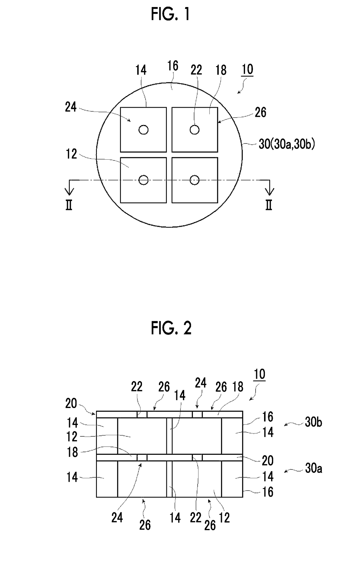
[0326]Instead of using the spacer 32 (acrylic frame body 16) of one layer interposed between the two single layer soundproof structures 30a and 30b in Example 1, the spacer 32 (acrylic frame body 16) of three layers interposed between the two single layer soundproof structures 30a and 30b was used, and the inter-film distance between layers of the single layer soundproof structures 30a and 30b was set to 9 mm, thereby forming a laminated soundproof structure. The measurement results of the transmission loss and the absorbance of the laminated soundproof structure are shown in FIGS. 13A and 13B. The maximum value of the transmission loss was one, and was 41 dB at 517 Hz (lamination shielding peak frequency). Accordingly, the transmission loss was larger than that of the single layer soundproof structure 30. The result is shown in Table 3.
[0327]The minimum value of the transmission loss due to the first natural vibration frequency of the two single layer soundproof structures 30a and ...
example 3
[0328]Instead of using the spacer 32 (acrylic frame body 16) of one layer interposed between the two single layer soundproof structures 30a and 30b in Example 1, the spacer 32 (acrylic frame body 16) of five layers interposed between the two single layer soundproof structures 30a and 30b was used, and the inter-film distance between layers of the single layer soundproof structures 30a and 30b was set to 15 mm, thereby forming a laminated soundproof structure. The measurement results of the transmission loss and the absorbance of the laminated soundproof structure are shown in FIGS. 14A and 14B. The maximum value of the transmission loss was 51 dB at 512 Hz. Accordingly, compared with the laminated soundproof structure of Example 2, the peak of transmission loss was further increased. The result is shown in Table 3.
[0329]As in Example 2, the minimum value of the transmission loss due to the first natural vibration frequency of the two single layer soundproof structures 30a and 30b wa...
examples 4 to 6
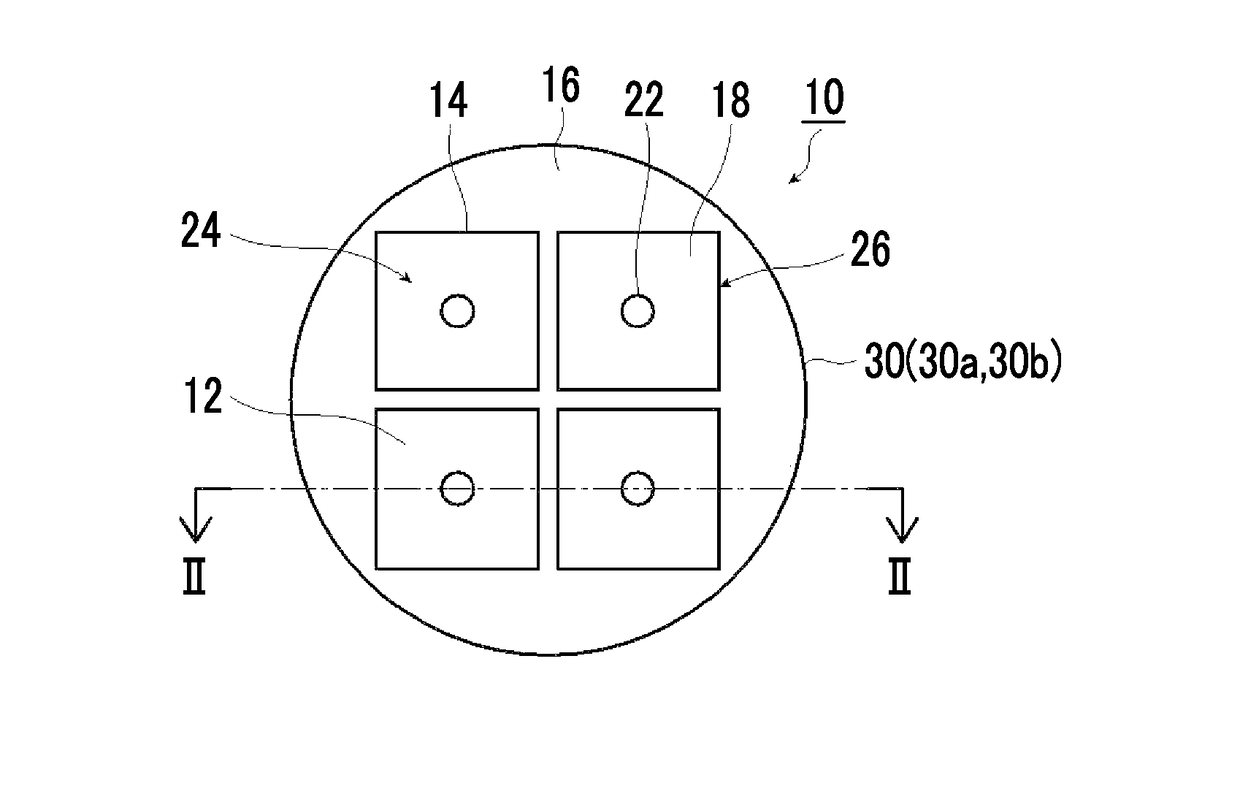
[0330]Instead of bonding a PET film having a thickness of 188 μm as the film 18 to an acrylic square frame having a frame size of 25 mm as the frame 14 in Example 1, a PET film having a thickness of 100 μm as the film 18 was bonded to an acrylic square frame having a frame size of 15 mm as the frame 14 and then the hole 22 was formed, thereby manufacturing a two-layer laminated soundproof structure.
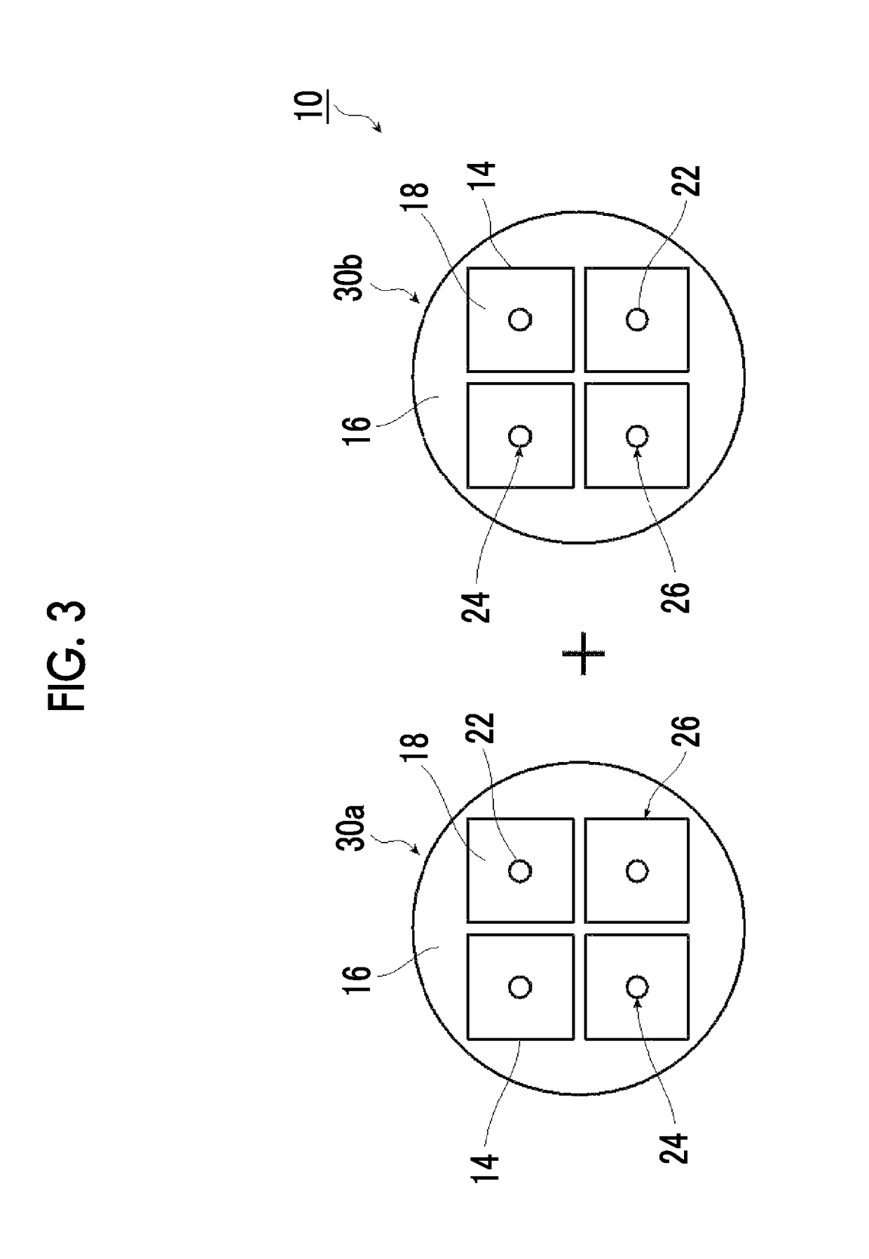
[0331]Incidentally, the region of the through-hole 12 of the frame 14 was not 4×4 but 2×2, and the PET film was fixed to the frame portion of the frame 14 using a double-sided tape. The hole 22 having a diameter of 1 mm was formed in a central portion of the film 18 of a unit cell, which is configured to include the frame 14 and the film 18, by punching. By repeating this step twice, two single layer soundproof structures 30 (30a and 30b) of the same conditions was able to be obtained.
[0332]Next, soundproof structures of Examples 4 to 8 of the present invention, each of which was a two-la...
PUM
| Property | Measurement | Unit |
|---|---|---|
| frequency | aaaaa | aaaaa |
| shielding | aaaaa | aaaaa |
| frequency | aaaaa | aaaaa |
Abstract
Description
Claims
Application Information