Supercharge Your Innovation With Domain-Expert AI Agents!

Fuel cell system

a fuel cell and system technology, applied in the field of fuel cell systems, can solve the problems of failure to execute the fail-safe processing, fail-safe processing, and cannot be executed when the switch is switched

Active Publication Date: 2018-04-26
TOYOTA JIDOSHA KK
View PDF2 Cites 1 Cited by
  • Summary
  • Abstract
  • Description
  • Claims
  • Application Information

AI Technical Summary

Benefits of technology

The patent text describes a fuel cell system that detects when there is an open failure in the relay that controls the voltage of the fuel cell. This open failure can occur when a switch connected between the fuel cell and the relay is short-circuited. When this happens, the fuel cell system initiates fail-safe processing to prevent damage to the system. The text also notes that some recent fuel cell systems have changed the location of the relay to make it closer to the motor, which eliminates the need for the open failure detection circuit. The technical effect of this patent is to provide a fuel cell system that can safely handle short-circated switches and relays, and without needing an extra circuit for detecting open failures.

Problems solved by technology

When the relay has the open failure, the fuel cell systems execute the fail-safe processing.
However, when the installation location of the relay is changed to the location loser to the motor than to the boost converter, the fail-safe processing, such as opening the relay to disconnect a short-circuit current from the fuel cell, cannot be executed when the switch is short-circuited.
When the fail-safe processing is not executed upon short-circuit of the switch, the short-circuit current continues to flow from the fuel cell, which causes overheating of component parts present on the route carrying the short-circuit current, which may result in failure.

Method used


Image

  • Fuel cell system
  • Fuel cell system
  • Fuel cell system

Examples


Embodiment Construction

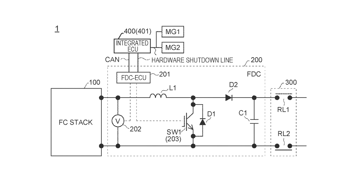
[0016]Hereinafter, an embodiment of the present disclosure will he described with reference to the drawings. First, the configuration of the present embodiment is described. FIG. 1 illustrates a configuration example of a fuel cell system 1 according to the embodiment of the present embodiment. The fuel cell system 1 according to the present embodiment is incorporated in a vehicle, the fuel cell system 1 being used to supply electric power generated in an FC stack 100 to a motor (not illustrated). Examples of the motor include a motor that drives driving wheels of the vehicle and a motor that drives an air compressor.

[0017]The fuel cell system 1 according to the present embodiment includes an FC stack 100, an FC boost converter (FDC) 200, an FC relay 300, integrated electronic control unit (ECU) 400, and motor generators MG1, MG2. The FC relay 300 is one example of the fuel cell relay connected to the FC stack 100.

[0018]The FC stack 100 is a fuel cell stack structured to include a p...


PUM


Abstract

A fuel cell system includes: a fuel cell stack; a voltage sensor configured to detect voltage of the fuel cell stack; a fuel cell relay connected to the fuel cell stack; a switch connected between the fuel cell stack and the fuel cell relay; an overcurrent detector configured to detect an overcurrent flowing to the switch; and a power generation stop device configured to stop power generation of the fuel cell stack when the overcurrent detector detects the overcurrent and the detected voltage becomes a specified value or less.

Description

INCORPORATION BY REFERENCE[0001]The disclosure of Japanese Patent Application No. 2016-209989 filed on Oct. 26, 2016 including the specification, drawings and abstract is incorporated herein by reference in its entirety.BACKGROUND1. Technical Field[0002]The present disclosure relates to a fuel cell system.2. Description of Related Art[0003]Fuel cell (FC) systems incorporated in a vehicle have been put in a practical use. For example, a fuel cell system disclosed in Japanese Patent Application Publication No. 2010-218953 includes a fuel cell, a relay that connects or disconnects a supply route of electric power generated in the fuel cell to a motor, a diode provided in a portion of the route closer to the motor than to the relay, the diode being configured to prevent current from flowing from the motor to the fuel cell, and a voltage sensor that detects voltage of the fuel cell. The fuel cell system determines whether or not the diode is in failure based on a difference in voltage de...

Claims


Application Information

Patent Timeline
IPC IPC(8): H01M8/04537G05F1/573
CPCH01M8/04559G05F1/573H01M8/04597H01M8/04955Y02E60/50
Inventor UMEHARA, TAKAHIROASO, SHINJI
Owner TOYOTA JIDOSHA KK
Features
  • R&D
  • Intellectual Property
  • Life Sciences
  • Materials
  • Tech Scout
  • Unparalleled Data Quality
  • Higher Quality Content
  • 60% Fewer Hallucinations
Learn More