
Lighting device, lighting device manufacturing method, and light distributor

a technology of lighting devices and manufacturing methods, which is applied in the direction of lighting support devices, lighting and heating apparatus, instruments, etc., can solve the problems of reducing the light usage efficiency of light sources, difficult to achieve the desired light distribution, and difficult control of the light distribution angle, so as to achieve a wide range of light distribution and inhibit the effect of the reduction of light usage efficiency

Active Publication Date: 2018-05-03
PANASONIC INTELLECTUAL PROPERTY MANAGEMENT CO LTD
View PDF6 Cites 9 Cited by
  • Summary
  • Abstract
  • Description
  • Claims
  • Application Information

AI Technical Summary

Benefits of technology

The present disclosure aims to improve the efficiency of a lighting device by controlling the distribution of light and preventing the scattering of light during sandblasting. This results in a broader distribution of light, which is useful for various applications. The disclosure provides a lighting device, method of manufacturing it, and a light distributor that can efficiently control the distribution of light and inhibit the reduction of light usage efficiency.

Problems solved by technology

However, in a conventional lighting device, it is conceivable to, for example, sandblast the light distribution converter panel to alter the form in which the light is emitted from the light source, but the broader the light distribution is, the more difficult the light distribution angle is to control, making it difficult to achieve the desired light distribution.
Moreover, when sandblasting is performed, light from the light source is scattered, which produces stray light and reduces the light usage efficiency of the light source.

Method used


Image

  • Lighting device, lighting device manufacturing method, and light distributor
  • Lighting device, lighting device manufacturing method, and light distributor
  • Lighting device, lighting device manufacturing method, and light distributor

Examples


embodiment

(Configuration)

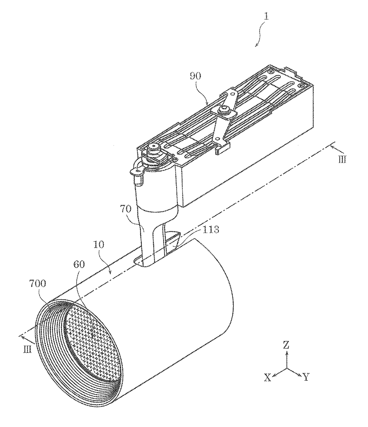
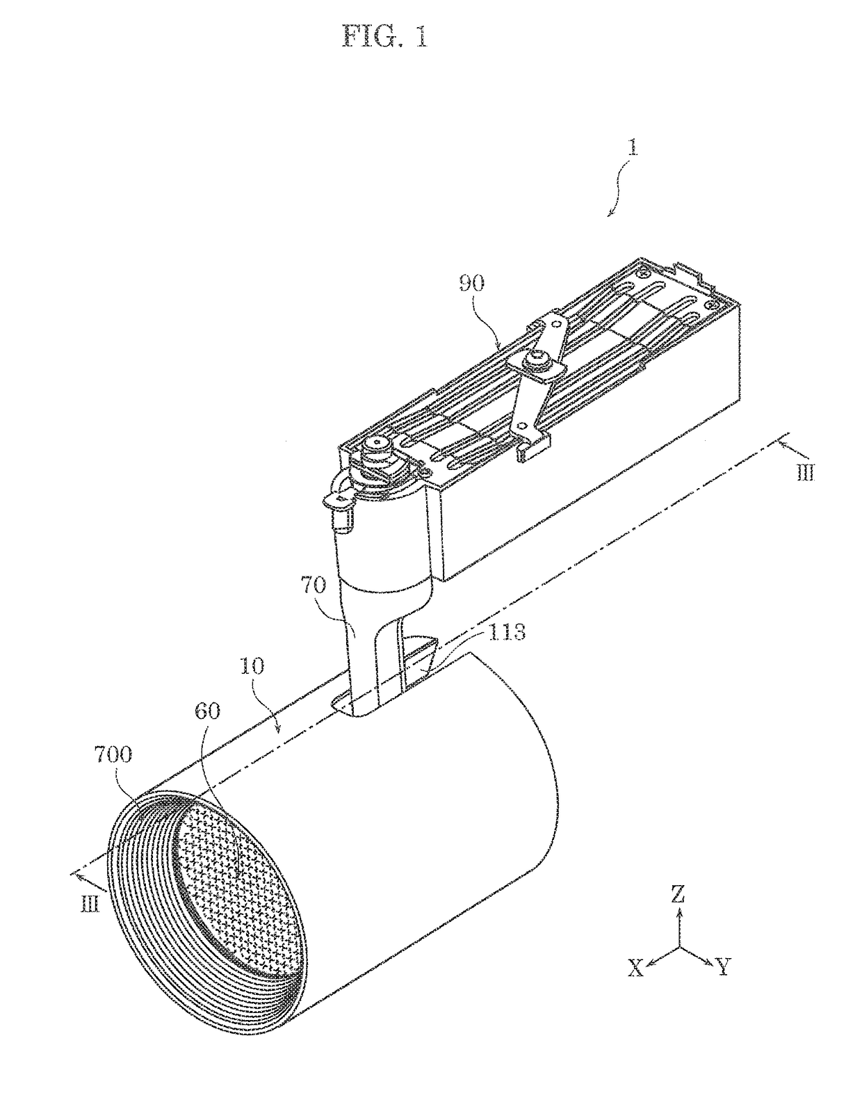
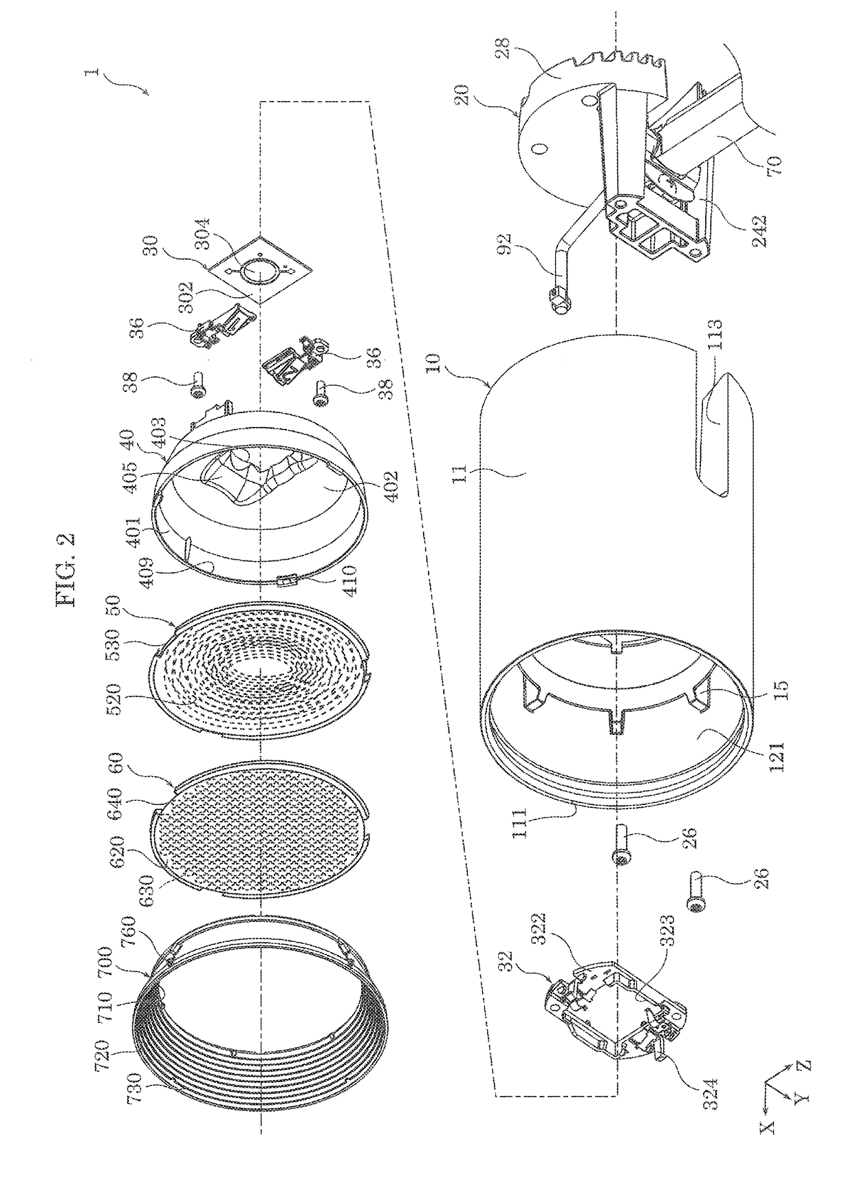
[0029]First, the configuration of lighting device 1 according to this embodiment will be described with reference to FIG. 1 through FIG. 6.

[0030]FIG. 1 is a perspective view of lighting device 1 according to the embodiment. FIG. 2 is an exploded perspective view of lighting device 1 according to the embodiment. FIG. 3 is a cross sectional view of lighting device 1 according to the embodiment, taken at line III-III in FIG. 1. FIG. 4 is a perspective view of light distributor 60 in lighting device 1 according to the embodiment. FIG. 5 is a cross sectional view of concave region 630 of light distributor 60 in lighting device 1 according to the embodiment. FIG. 6 is a conceptual diagram of concave regions 630 of light distributor 60 in lighting device 1 according to the embodiment.

[0031]In FIG. 1, in lighting device 1, the lengthwise direction of the lamp body corresponds to the X axis, the widthwise direction of the lamp body corresponds to the Y axis, and the up and dow...


PUM


Abstract

A lighting device includes a light source and a light distributor disposed on a light emission side of the light source. The light distributor includes an entrance surface through which light enters and an exit surface through which the light that enters through the entrance surface exits. At least one of the entrance surface and the exit surface includes concave regions. Each of the concave regions includes a smooth concave surface. The concave regions control distribution of light from the light source that is refracted or reflected by an optical lens or a reflective component.

Description

CROSS REFERENCE TO RELATED APPLICATION[0001]This application claims the benefit of priority of Japanese Patent Application Number 2016-211007 filed on Oct. 27, 2016, the entire content of which is hereby incorporated by reference.BACKGROUND1. Technical Field[0002]The present disclosure relates to a lighting device, a lighting device manufacturing method, and a light distributor.2. Description of the Related Art[0003]A lighting device including a light source and a light distribution converter panel that alters the light distribution of the light source is known (for example, see Japanese Patent No. 5698861).[0004]With this lighting device, it is possible to alter the form in which the light is emitted from the light source by attaching light distribution converter panel.SUMMARY[0005]However, in a conventional lighting device, it is conceivable to, for example, sandblast the light distribution converter panel to alter the form in which the light is emitted from the light source, but ...

Claims


Application Information

Patent Timeline
Patent Type & Authority Applications(United States)
IPC IPC(8): F21V13/04G02B7/02F21V21/04F21V17/06F21S8/02F21V19/02F21V5/04
CPCF21V13/04G02B7/02F21V21/04F21V17/06F21S8/02F21V19/02F21V5/04F21K9/20F21K9/68F21Y2115/10F21S8/00F21V5/004F21V5/045F21V21/28F21V23/002F21V5/008F21V21/30F21Y2115/20F21Y2115/15G02B3/08G02B27/0938G02B27/095G02B27/0983
Inventor YAMAE, KAZUYUKI
Owner PANASONIC INTELLECTUAL PROPERTY MANAGEMENT CO LTD
Learn More