RF shield for reducing eddy current in a pet-mr imaging system

a technology of eddy current reduction and rf shield, which is applied in the field of magnetic resonance (mr) imaging, can solve the problems of affecting the performance of any thermally sensitive parts, mutual annihilation, discomfort of the subject being imaged, etc., and achieves the effect of reducing the surface temperature of the rf shield

Active Publication Date: 2018-05-03
GE PRECISION HEALTHCARE LLC
View PDF3 Cites 2 Cited by
  • Summary
  • Abstract
  • Description
  • Claims
  • Application Information

AI Technical Summary

Benefits of technology

[0011]In accordance with another aspect of the invention, an RF coil assembly for use in a stand-alone or hybrid MRI system includes a generally cylindrical RF coil former having an inner surface and an outer surface, an RF shield affixed to the outer surface of the RF coil former and configured to conform to the outer surface thereof, and an RF coil affixed to an inward facing surface of the RF coil former. The RF shield of the RF coil assembly further includes a plurality of longitudinal slits cut in the RF shield extending in a z-direction along the RF shield and a plurality of circumferential slits cut in the RF shield extending in a circumferential direction along the RF shield, wherein the plurality of longitudinal slits and the plurality of circumferential slits are configured to disrupt the formation of gradient field induced eddy currents on the RF shield, so as to thereby reduce a surface temperature of the RF shield.

Problems solved by technology

As these positrons travel through the tissues of the subject, they lose kinetic energy and ultimately collide with an electron, resulting in mutual annihilation.
The eddy current generated on the RF shield produces heat that create high temperature profiles that affect the performance of any thermally sensitive parts located on or near the RF shield, such as the PET detector modules.
The eddy current generated on the RF shield also raises the overall temperature of the patient bore, which may potentially cause discomfort to a subject being imaged.

Method used


Image

  • RF shield for reducing eddy current in a pet-mr imaging system
  • RF shield for reducing eddy current in a pet-mr imaging system
  • RF shield for reducing eddy current in a pet-mr imaging system

Examples


Embodiment Construction

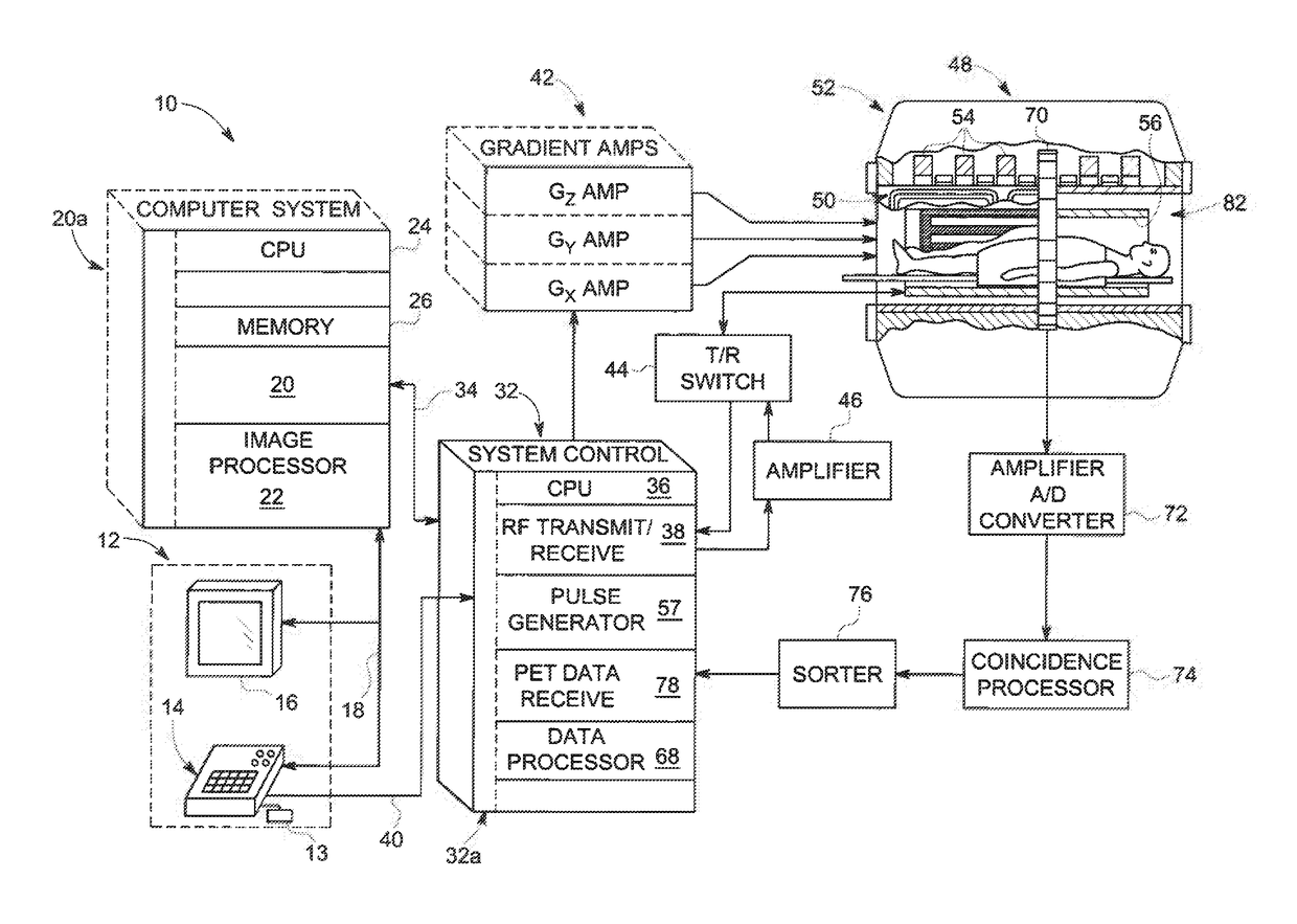
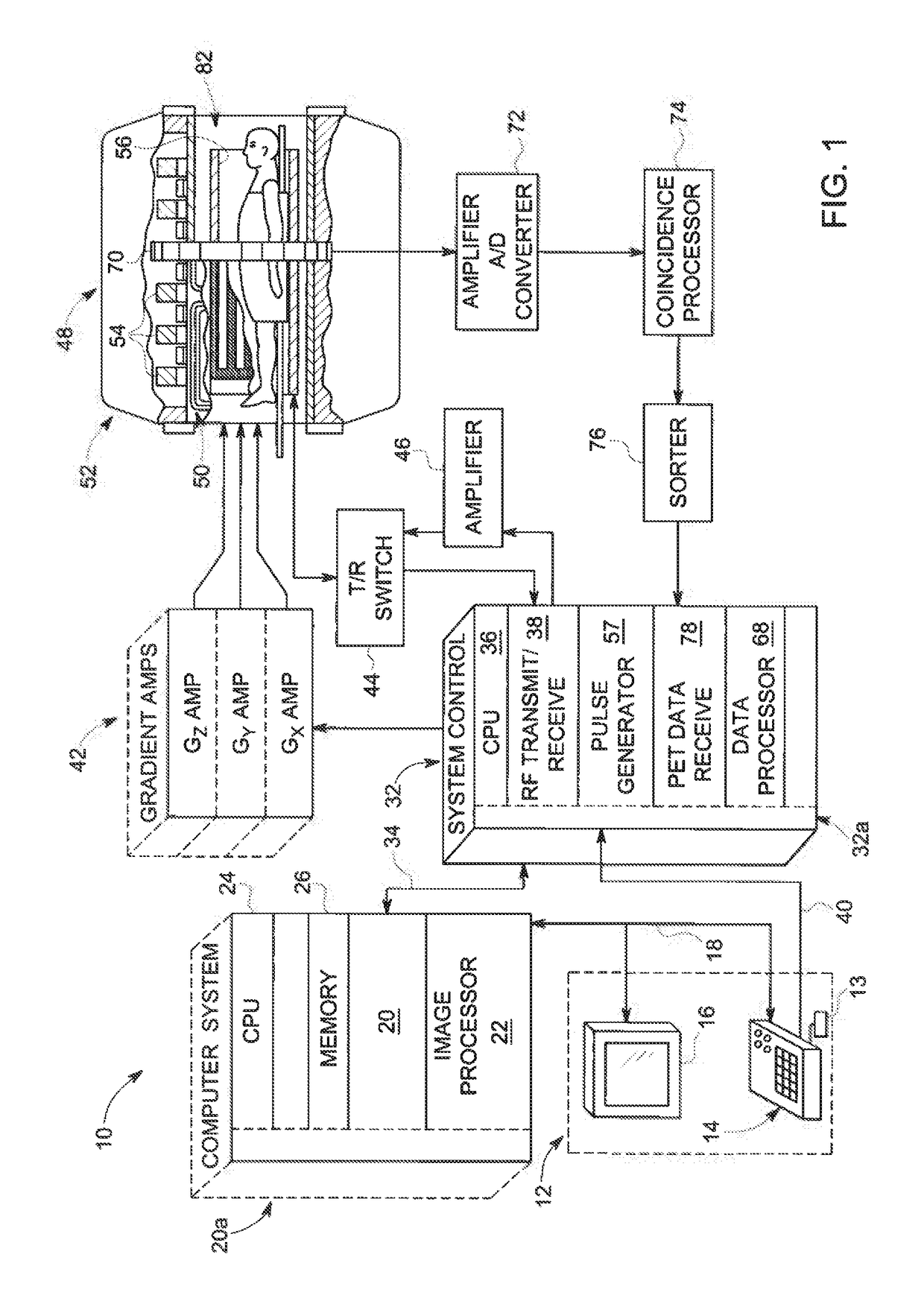
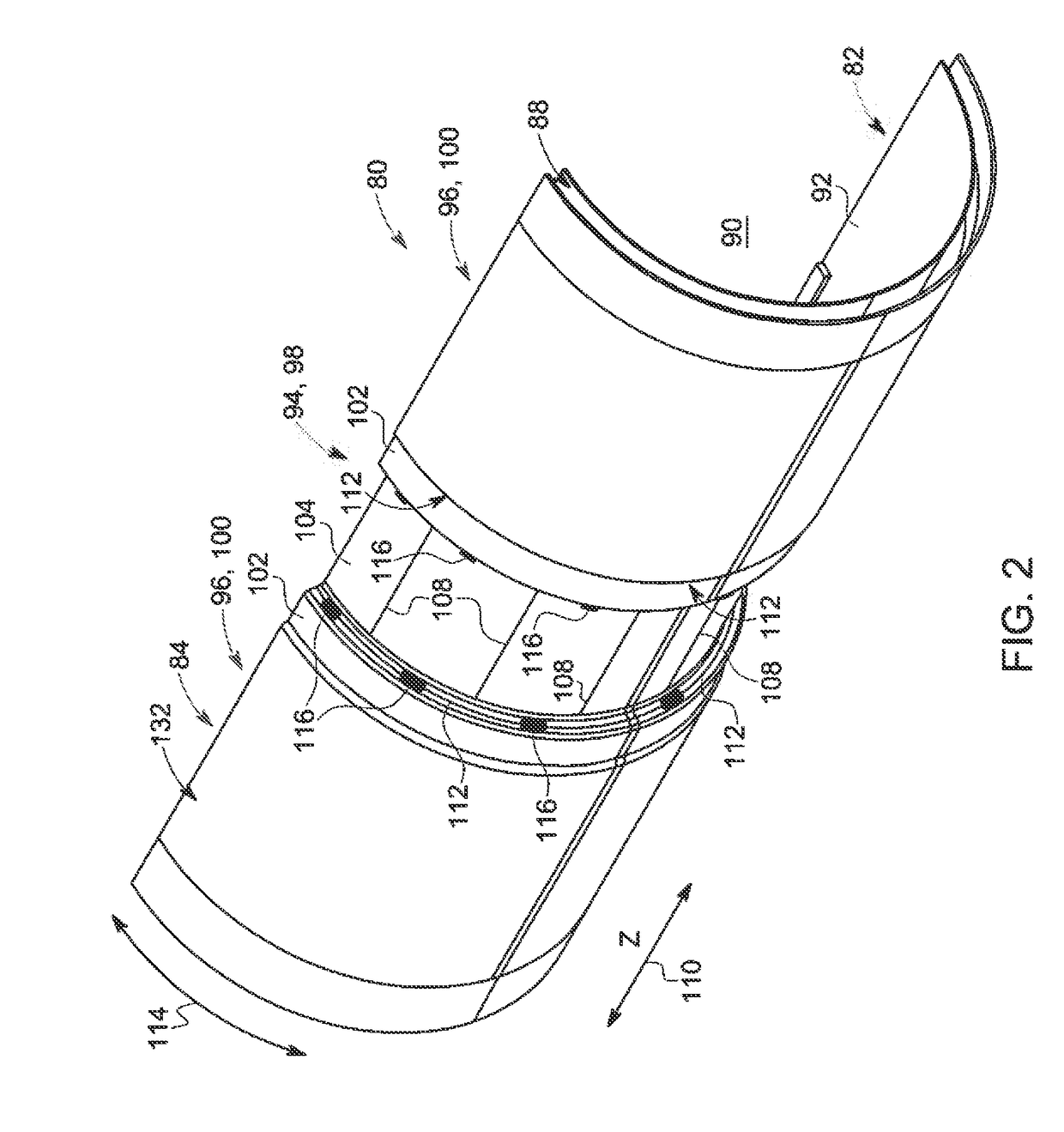
[0021]An RF coil assembly is provided that includes an RF shield having a plurality of slits formed therein that are configured to prevent the generation of high temperature profiles on the surface of the RF shield. Longitudinal slits and / or circumferential slits are formed in the RF shield that disrupt the formation of eddy currents on the RF shield surface, so as to reduce the heat produced from such eddy currents and prevent the generation of the high temperature profiles that affect the performance of any thermally sensitive parts located on or near the RF shield, such as PET detector modules.

[0022]According to embodiments of the invention, the RF coil assembly can be implemented in a variety of imaging systems or apparatuses. For example, the RF coil assembly can be incorporated into a stand-alone MR imaging system or can be incorporated into a hybrid MR imaging system, such as a hybrid PET-MR imaging system, for example. Thus, while embodiments of the invention are set forth h...


PUM


Abstract

An imaging apparatus is disclosed that includes an MRI system, either as a stand-alone system or hybrid PET-MRI system. The MRI system includes gradient coils positioned about a patient bore, an RF coil former comprising an inner surface and an outer surface, an RF shield positioned on the outer surface of the RF coil former so as to be formed about the RF coil former, and an RF coil positioned on the inner surface of the RF coil former and about the patient bore, with the RF coil coupled to a pulse generator to emit an RF pulse sequence and receive resulting MR signals from a subject of interest. The RF shield includes a plurality of slits formed therein configured to disrupt the formation of gradient field induced eddy currents on the RF shield, so as to prevent the generation of high temperature profiles on the surface of the shield

Description

CROSS-REFERENCE TO RELATED APPLICATIONS[0001]This application is a divisional of U.S. patent application Ser. No. 13 / 927,617, filed on Jun. 26, 2013, the disclosure of which is incorporated herein by reference in its entirety.BACKGROUND[0002]Embodiments of the invention relate generally to magnetic resonance (MR) imaging, and more specifically, to an RF shield configured to prevent the generation of high temperature profiles on the surface thereof resulting from eddy current heating, so as to minimize impact on the performance of thermally sensitive parts, such as a positron emission tomography (PET) detector array in a hybrid PET-MRI system.[0003]MR imaging involves the use of magnetic fields and excitation pulses to detect the free induction decay of nuclei having net spins. When a substance such as human tissue is subjected to a uniform magnetic field (polarizing field B0), the individual magnetic moments of the spins in the tissue attempt to align with this polarizing field, but...

Claims


Application Information

Patent Timeline
Patent Type & Authority Applications(United States)
IPC IPC(8): G01R33/422A61B5/00A61B6/00A61B5/055G01R33/48A61B6/03
CPCA61B5/0035A61B6/4258A61B6/4275A61B5/055A61B6/4417G01R33/422G01R33/481A61B6/037G01R33/56518
Inventor SAHA, SAIKAT
Owner GE PRECISION HEALTHCARE LLC
Why Eureka
Try Eureka