Room model extraction device, room model extraction system, computer readable medium, and room model extraction method

a technology for extracting devices and room models, which is applied in the direction of instruments, heating types, configuration cad, etc., can solve the problems of increasing calculation time, consuming a lot of work time, and burdening work tim

Inactive Publication Date: 2018-05-03
MITSUBISHI ELECTRIC CORP
View PDF1 Cites 10 Cited by
  • Summary
  • Abstract
  • Description
  • Claims
  • Application Information

AI Technical Summary

Benefits of technology

[0010]A room model extraction device according to the present invention includes an extraction unit, which allows easy extraction of a room model from three-dimensional building data.

Problems solved by technology

This method, however, has a problem in that specification of a large number of components of a room, such as a wall, a floor, and a ceiling, is necessary for each room, which is a burden on work time.
The conventional method saves the labor of specifying each of building members, but still requires the work of specifying a room, which takes much work time for a building having a large number of rooms or the like.
Furthermore, in a case where thermal load calculation is performed using an extracted room model, there is also a problem in which a part such as a gap between building members, which has little influence on the calculation accuracy but increases the calculation time, is included.

Method used


Image

  • Room model extraction device, room model extraction system, computer readable medium, and room model extraction method
  • Room model extraction device, room model extraction system, computer readable medium, and room model extraction method
  • Room model extraction device, room model extraction system, computer readable medium, and room model extraction method

Examples


first embodiment

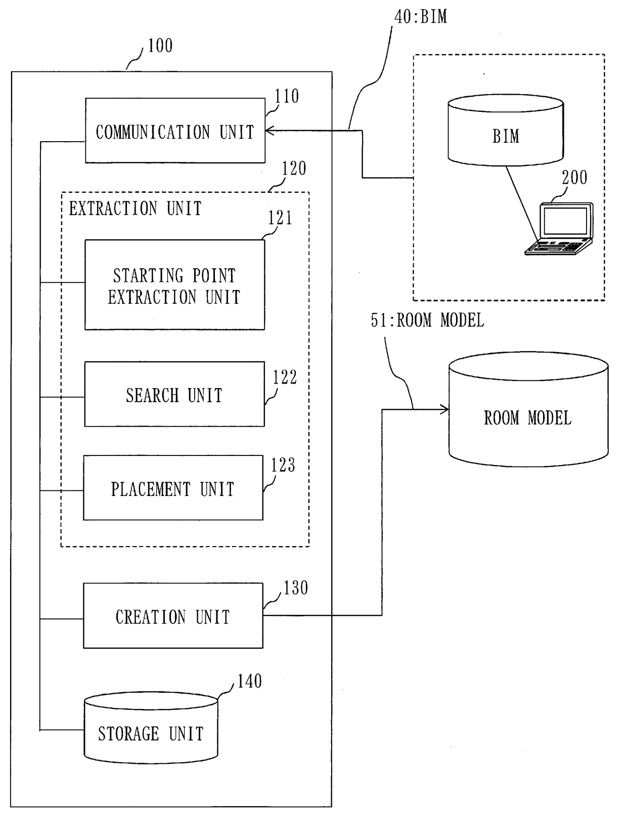
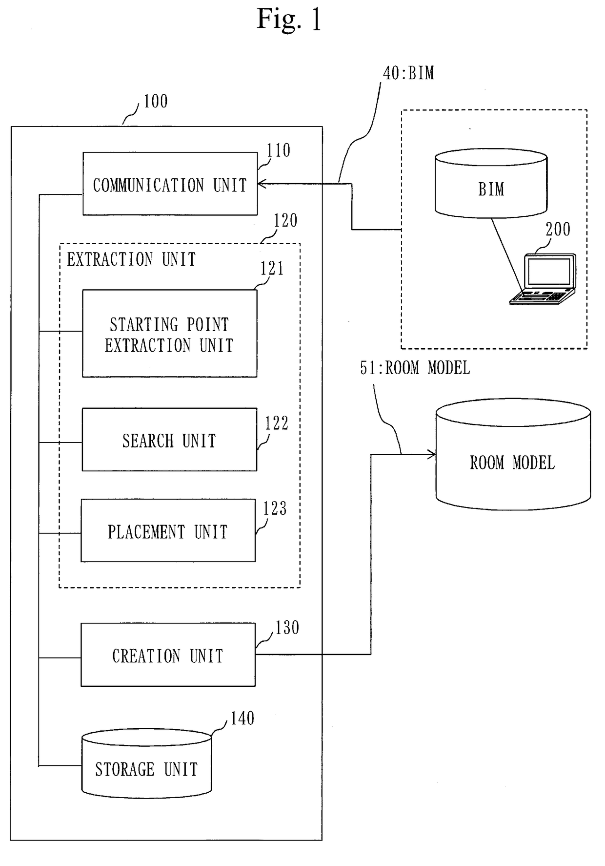
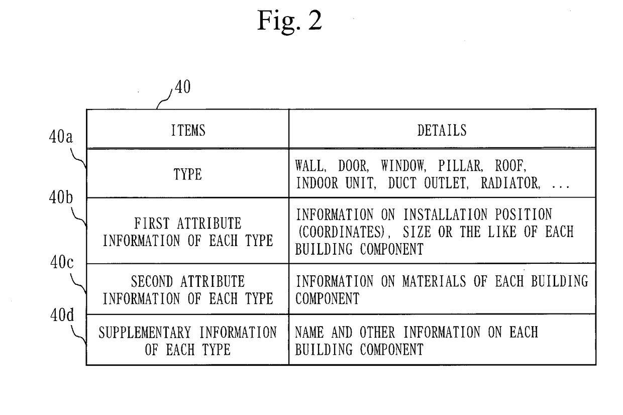
[0032]A first embodiment will be described with reference to FIGS. 1 to 19. The first embodiment relates to a room model extraction device 100 to extract a room model from a building information model, which is three-dimensional building data. A room model can be readily extracted from the building information model by the room model extraction device 100, which improves the processing efficiency of thermal load calculation. The building information model will be referred to a BIM below. While the BIM is used in the embodiment described below, the three-dimensional building data are not limited to the BIM, but may be other three-dimensional CAD data. Note that the BIM or the three-dimensional CAD data refer to three-dimensional building data including a plurality of building components constituting a building having rooms, and attribute information of each of the building components.

[0033]

[0034]FIG. 1 is a block diagram of the room model extraction device 100. The room model extract...

second embodiment

[0091]The second embodiment will be described with reference to FIGS. 20 and 21.

[0092]FIG. 20 illustrates an example hardware configuration of a room model extraction device 100 implemented by a computer. Description will now be made with reference to FIG. 20. The room model extraction device 100, which is a computer, includes hardware such as a processor 901, an auxiliary storage unit 902, a memory 903, a communication unit 904, an input interface 905, and a display interface 906. The processor 901 is connected with the other hardware components via a signal line 910, and controls the other hardware components. The input interface 905 is connected to the input device 907. The display interface 906 is connected to a display 908.

[0093]The processor 901 is an integrated circuit (IC) to perform processing. The processor 901 is, for example, a central processing unit (CPU), a digital signal processor (DSP), or a graphics processing unit (GPU). The auxiliary storage unit 902 is, for exam...


PUM


Abstract

An extraction unit (120) extracts a starting component from a BIM (40) that is a building information model. The extraction unit (120) searches for a plurality of building components adjacent to each other, with respect to the BIM (40), by starting from the starting component, and extracts a virtual room constituted by virtual members from the BIM (40) by placing a virtual member on each of a plurality of building components obtained as a search result. The creation unit (130) sets, for each of the virtual members in the virtual room, a piece of attribute information associated with the building component on which the virtual member is placed from among pieces of attribute information included in the BIM (40), and creates a virtual room, in which pieces of attribute information are set, as a room model (51).

Description

TECHNICAL FIELD[0001]The present invention relates to a room model extraction device, a room model extraction system, a room model extraction program, and a room model extraction method to extract a room from three-dimensional building data such as BIM data.BACKGROUND ART[0002]A mainstream method for extracting a room model from three-dimensional building data has been a method of manually selecting respective objects (building members) and extracting the selected objects as a room. This method, however, has a problem in that specification of a large number of components of a room, such as a wall, a floor, and a ceiling, is necessary for each room, which is a burden on work time. To address the problem, Patent Literature 1 discloses a system for searching for building members radially from a position specified by a user and setting a boundary of a room.[0003]The conventional method saves the labor of specifying each of building members, but still requires the work of specifying a ro...

Claims


Application Information

Patent Timeline
Patent Type & Authority Applications(United States)
IPC IPC(8): G06F17/50G06T17/10
CPCG06F17/5004G06T17/10F24F11/63F24F2110/10F24F11/30G06F2217/02G06F2111/20G06F30/13G06F30/00
Inventor SUNADA, HIDEYUKI
Owner MITSUBISHI ELECTRIC CORP
Why Eureka
Try Eureka