Communications system

a communication system and communication technology, applied in the field of communication devices, can solve the problems of wasting resources, rrc signaling may not be suited for this purpose, and the battery saving in the ue will be less,

Active Publication Date: 2018-05-03
NEC CORP
View PDF3 Cites 0 Cited by
  • Summary
  • Abstract
  • Description
  • Claims
  • Application Information

AI Technical Summary

Benefits of technology

[0004]The present invention provides a simple mechanism by which the e

Problems solved by technology

However we see this as wastage of the resources.
As the component carriers a UE may monitor may change frequently RRC signaling may not be a suited for this pur

Method used


Image

  • Communications system
  • Communications system
  • Communications system

Examples


Embodiment Construction

[0024]Overview

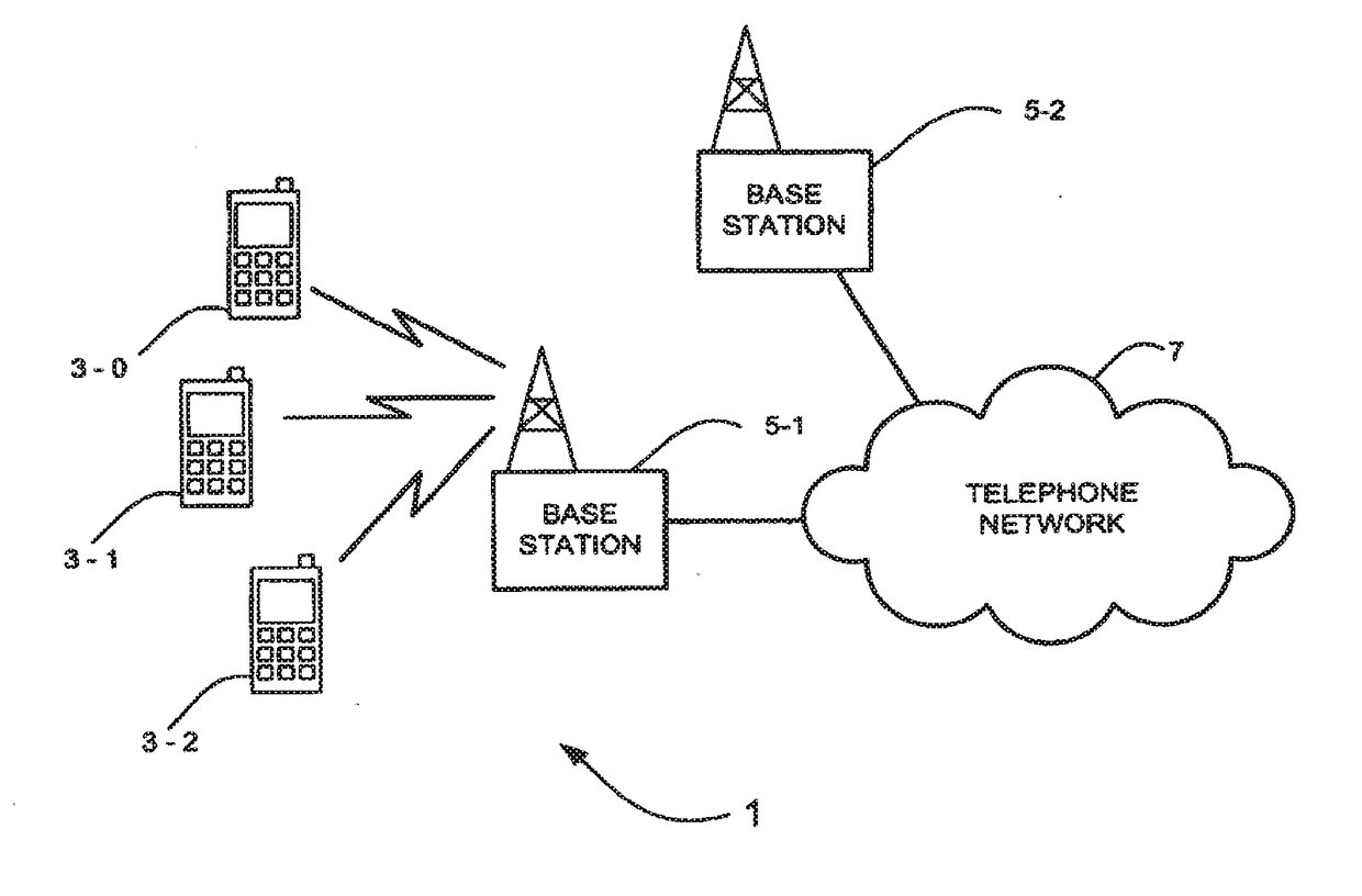
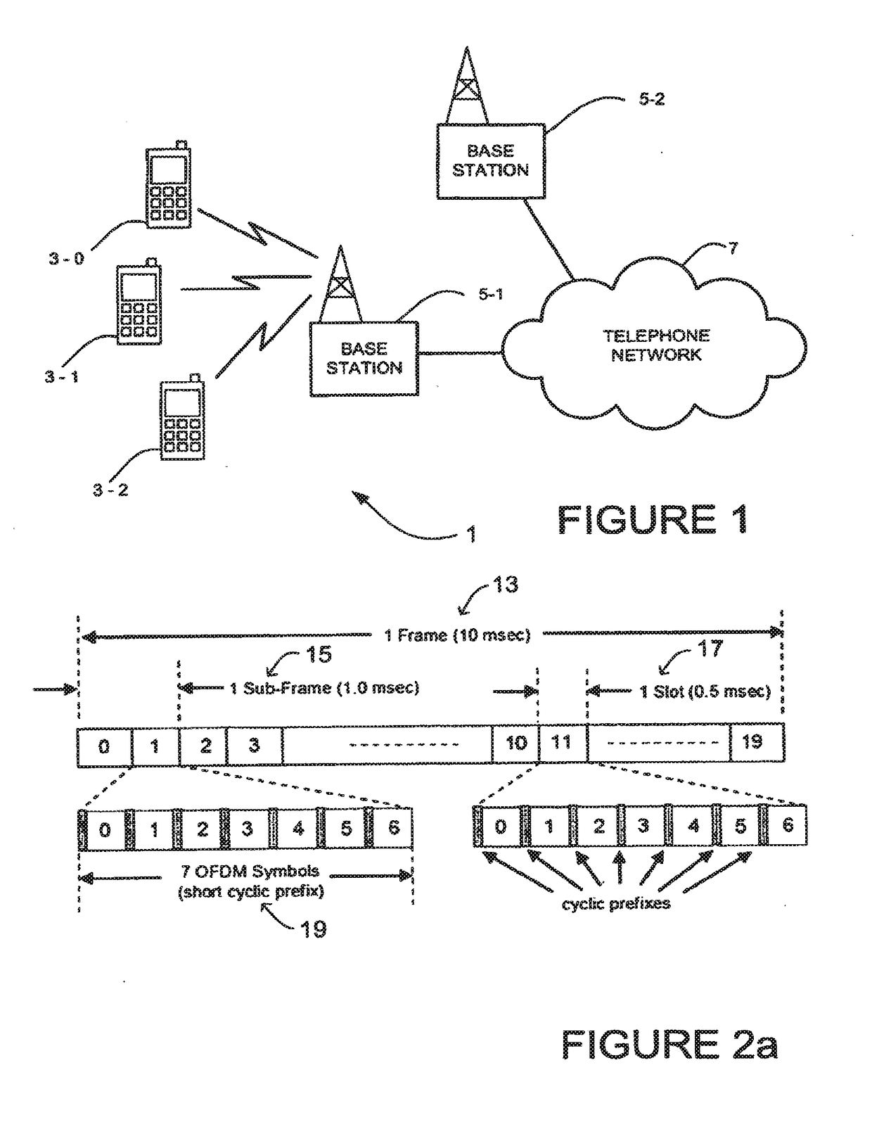
[0025]FIG. 1 schematically illustrates a mobile (cellular) telecommunication system 1 in which users of mobile telephones (MT) 3-0, 3-1, and 3-2 can communicate with other users (not shown) via one of the base stations 5-1 or 5-2 and a telephone network 7. A number of uplink and downlink communications resources (sub-carriers, time slots etc) are available for the wireless link between the mobile telephones 3 and the base stations 5. In this exemplary embodiment, the base stations 5 allocate downlink resources to each mobile telephone 3 depending on the amount of data to be sent to the mobile telephone 3. Similarly, the base stations 5 allocate uplink resources to each mobile telephone 3 depending on the amount and type of data the mobile telephone 3 has to send to the base station 5.

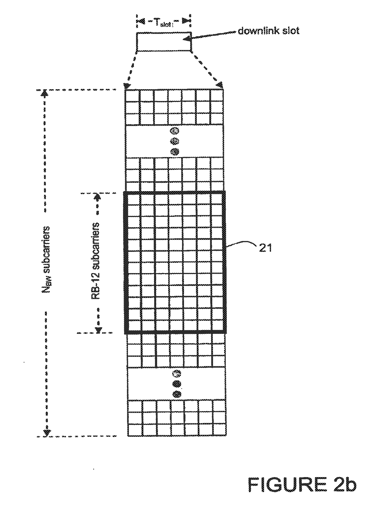
[0026]In this exemplary embodiment, the system bandwidth is divided into five 20 MHz sub-bands, each being carried by a respective component carrier. The base station 5 is operable to allo...


PUM


Abstract

A mobile communications system is proposed in which mobile communications devices are arranged to transmit signals to and to receive signals from a base station using one or a subset of available sub-bands, with the base station being configured to move the mobile communications devices between the sub-bands. An anchor sub-band is also provided on which idle mobile communications devices camp until they are moved to one or more other sub-bands in addition to or instead of the anchor sub-band.

Description

TECHNICAL FIELD[0001]The present invention relates to communications devices, particularly but not exclusively devices operating according to the 3GPP standards or equivalents or derivatives thereof. The invention has particular but not exclusive relevance to the impacts of carrier aggregation that is to be used in LTE-Advanced as currently defined in 3GPP standards documentation TR 36.814.BACKGROUND ART[0002]With LTE Rel 8, a transmission band of 20 MHz was defined. In LTE-Advanced carrier aggregation will be used to support system bandwidths up to 100 MHz. This involves splitting the system bandwidth into five 20 MHz sub-bands, each centred on a respective component carrier. In order to be backwards compatible with LTE Rel 8 User Equipment (UEs), at least one of those sub-bands has to be LTE Rel 8 compliant.[0003]To support carrier aggregation a new Physical Downlink Control Channel (PDCCH) structure is needed to address the aggregated system bandwidth of up to 100 MHz. Two differ...

Claims


Application Information

Patent Timeline
IPC IPC(8): H04W72/04H04W72/00H04W48/12H04W36/06H04W68/00H04W88/02H04W88/08
CPCH04W88/08H04W88/02H04W72/0453H04W36/06H04W72/005H04W68/00H04W48/12H04W72/042H04W72/53H04L5/0098H04L5/0023H04L5/001H04L5/0053H04L5/0087H04W72/23Y02D30/70H04W74/04H04W76/28H04W72/121H04W72/30
Inventor AHLUWALIA, JAGDEEP SINGHARNOTT, ROBERT
Owner NEC CORP
Why Eureka
Try Eureka