Welding system providing visual and audio cues to a welding helmet with a display

a welding helmet and display technology, applied in the field of welding equipment, can solve the problems of not being able to achieve the desired closeness, the welding machine may not be located close to the work space, and the monitor consisting only of audio arc parameter indicators is difficult to hear and interpola

Active Publication Date: 2018-05-10
LINCOLN GLOBAL INC
View PDF41 Cites 21 Cited by
  • Summary
  • Abstract
  • Description
  • Claims
  • Application Information

AI Technical Summary

Benefits of technology

[0004]In manual or semi-automated welding a user / operator (i.e. welder) directs welding equipment to make a weld. For example, in arc welding the welder may manually position a welding rod or welding wire and produce a heat generating arc at a weld location. In this type of welding the spacing of the electrode from the weld location is related to the arc produced and to the achievement of optimum melting / fusing of the base and welding rod or wire metals. The quality of such a weld is often directly dependent upon the skill of the welder.
[0005]Welders generally rely upon a variety of information when welding. This information includes, for example, current and voltage. Traditionally, welders would need to look at gauges on the control panel of the welding equipment to gain this information. This would require the welder to direct their field of vision away from the welding work area and as such was undesirable. In addition, in many cases, the welding machine may not be located close to the work space. In such cases, the welding machine is operated by a cable-connected remote control that can be used to change parameters such as, e.g., welding power, polarity, arc characteristics, etc. However, before the process can be set up, the welder may need to see the display readouts that are physically located on the machine. The setting-up process may require many trips before the set-up is completed.
[0006]In the past, efforts have been made to provide welders with information during welding, such as in the method disclosed in U.S. Pat. No. 4,677,277, where current and voltage are monitored to produce an audio indication to the operator as to the condition of the arc in arc welding. However, monitors consisting only of audio arc parameter indicators are hard to hear and interpolate and are not capable of achieving the desired closeness of control and quality of weld often required.

Problems solved by technology

This would require the welder to direct their field of vision away from the welding work area and as such was undesirable.
In addition, in many cases, the welding machine may not be located close to the work space.
However, before the process can be set up, the welder may need to see the display readouts that are physically located on the machine.
However, monitors consisting only of audio arc parameter indicators are hard to hear and interpolate and are not capable of achieving the desired closeness of control and quality of weld often required.
In addition, related art welding devices have limited guidance with respect to aiding the welder, whether a beginner or exercised, as the weld is being performed.

Method used


Image

  • Welding system providing visual and audio cues to a welding helmet with a display
  • Welding system providing visual and audio cues to a welding helmet with a display
  • Welding system providing visual and audio cues to a welding helmet with a display

Examples


Embodiment Construction

[0038]Exemplary embodiments of the invention will now be described below by reference to the attached Figures. The described exemplary embodiments are intended to assist the understanding of the invention, and are not intended to limit the scope of the invention in any way. Like reference numerals refer to like elements throughout.

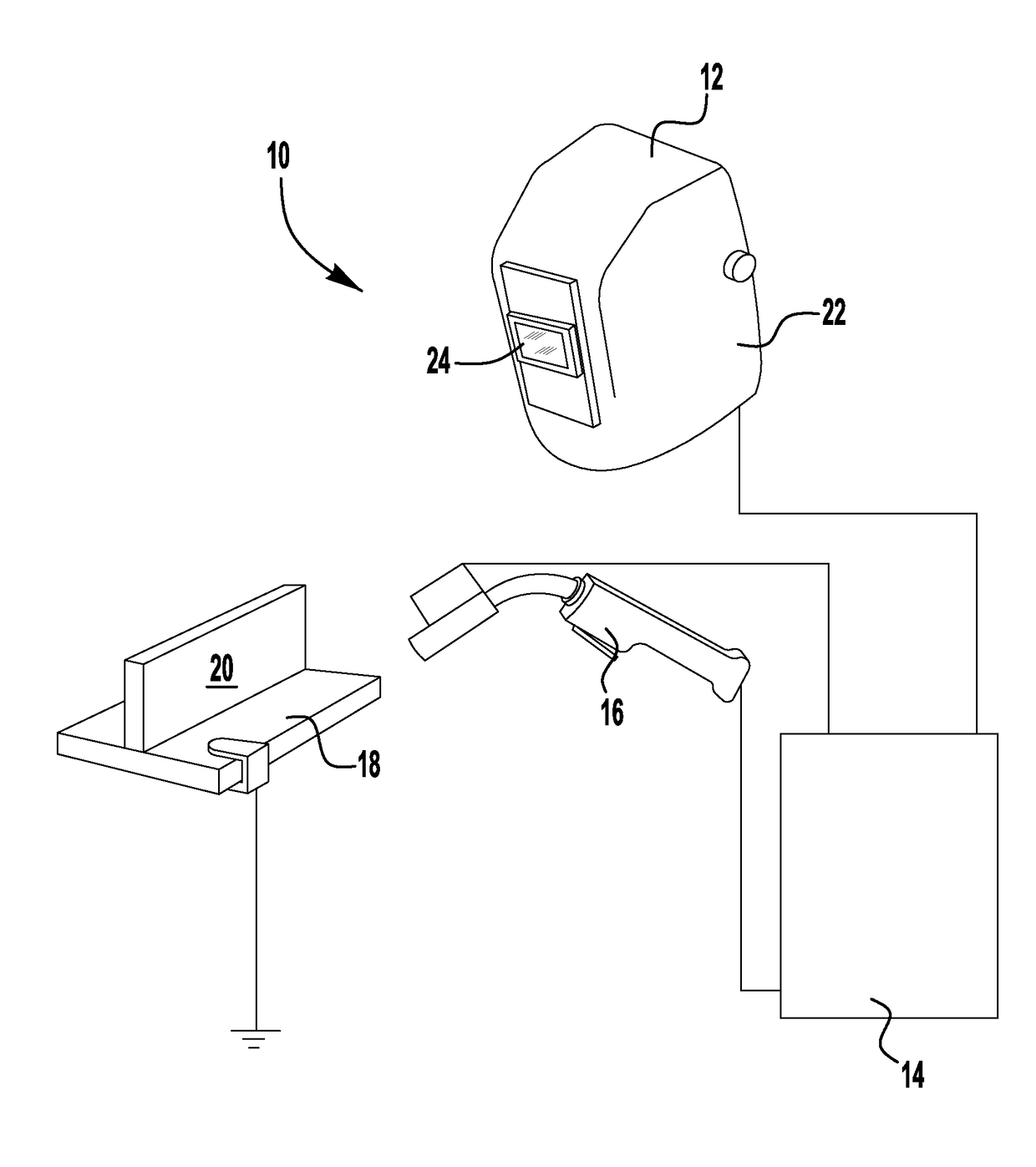
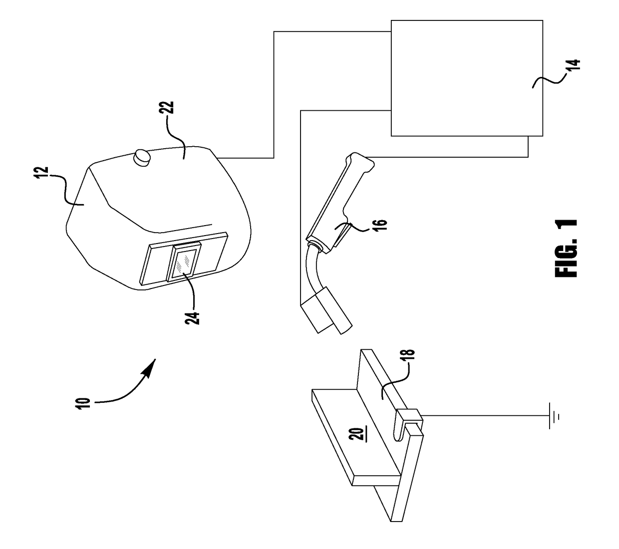
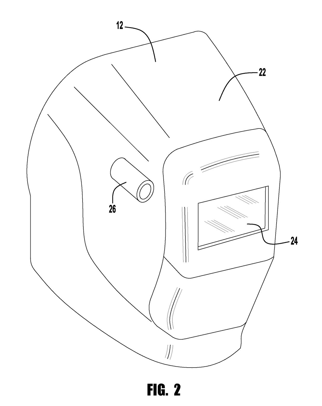
[0039]Referring now to the drawings, there is illustrated in FIG. 1 a welding system 10. The welding system 10 includes a welding helmet 12, a welding system 14, a welding gun 16 and a work piece 18. The work piece 18 generally defines a welding work area 20 where the welding gun 16 may be used to form a weld.

[0040]The welding system 14 includes welding equipment for generating a welding current and voltage, a welding control system for controlling the welding current and voltage, and a monitoring system for monitoring the welding current and voltage. That is, the welding system, can be on known or used welding power supply having a known construction and ...


PUM

PropertyMeasurementUnit
distanceaaaaaaaaaa
coloraaaaaaaaaa
shapeaaaaaaaaaa

Abstract

A system for aiding a user in at least one of welding, cutting, joining, and cladding operations is provided. The system includes a welding tool and a welding helmet with a face-mounted display. The system also includes a spatial tracker configured to track the welding helmet and the welding tool in 3-D space relative to an object to be worked on. A processor based subsystem is configured to generate visual cues based on information from the spatial tracker and transmit the visual cues to a predetermined location on the face-mounted display.

Description

PRIORITY AND INCORPORATION BY REFERENCE[0001]This U.S. Non-Provisional Patent Application claims priority to pending U.S. Provisional Application Ser. No. 62 / 418,737, filed Nov. 7, 2016, which is incorporated herein by reference in its entirety. The specifications of U.S. application Ser. No. 14 / 682,340, filed Apr. 9, 2015; U.S. application Ser. No. 14 / 037,699, filed Sep. 26, 2013; U.S. application Ser. No. 12 / 577,824, filed on Oct. 13, 2009, which issued as U.S. Pat. No. 8,569,655; and U.S. Provisional Patent Application No. 61 / 977,275, filed Apr. 9, 2014, are incorporated herein by reference in their entirety.BRIEF SUMMARY OF THE INVENTIONField of the Invention[0002]This invention relates in general to equipment used in welding. Devices, systems, and methods consistent with the invention relate to the monitoring of welding parameters and specifically to a welding system that provides visual and audio cues to a display located in the welder's helmet.Description of the Related Art[0...

Claims


Application Information

Patent Timeline
Patent Type & Authority Applications(United States)
IPC IPC(8): B23K9/095A61F9/06G02B27/01G05B19/18G08B3/10G06T11/60G06K9/00
CPCB23K9/0953A61F9/064B23K9/0956G02B27/0172G05B19/182G08B3/10G06T11/60G06K9/00671G02B2027/0138G02B2027/0141G02B2027/014G05B2219/45135G05B2219/45044G06F3/0482A61F9/06B23K9/1087B23K9/322G09B19/24G06V20/20
Inventor MEESS, BRIANEVANS, SARAH
Owner LINCOLN GLOBAL INC
Why Eureka
Try Eureka