Pneumatic tire

a pneumatic tire and tire body technology, applied in the field of pneumatic tires, can solve the problems of low rolling resistance, achieve the effects of reducing energy loss, low loss tangent, and high loss tangen

Active Publication Date: 2018-05-10
SUMITOMO RUBBER IND LTD
View PDF12 Cites 1 Cited by
  • Summary
  • Abstract
  • Description
  • Claims
  • Application Information

AI Technical Summary

Benefits of technology

[0012]In the tire according to the present invention, the sidewall having a low loss tangent extends to a position between the bead and the chafer. In the tire, the chafer having a high loss tangent is made small. In the tire, energy loss is reduced. In the tire, rolling resistance is low.
[0013]In the tire according to the present invention, the chafer having a high complex elastic modulus extends to a position outward of the end of the turned-up portion in the radial direction. The chafer inhibits a portion near the end of the turned-up portion from being moved. The chafer reduces concentration of distortion on the end of the turned-up portion. In the tire, PTL is inhibited.
[0014]In the tire according to the present invention, the outline of the side surface of the chafer includes the arc C that extends outward from the heel of the bead portion in the radial direction and projects inward. The shape allows the bead portion and a rim to be in close contact with each other when the tire is mounted on the rim. Furthermore, the sidewall, which extends to a position between the bead and the chafer, allows the flange and the chafer in which the outline of the side surface includes the arc C to effectively come into close contact with each other. In the tire, the arc C formed in the outline of the side surface and the sidewall that extends to a position inward of the chafer in the axial direction effectively inhibits the bead portion from being moved. Distortion is inhibited in a portion, of the chafer, outward of the end of the turned-up portion. Even in a portion, of the chafer, which contacts with air, crack is inhibited from growing. In the tire, the excellent quality of the appearance is maintained.

Problems solved by technology

In the tire, rolling resistance is low.

Method used


Image

  • Pneumatic tire
  • Pneumatic tire
  • Pneumatic tire

Examples


example 1

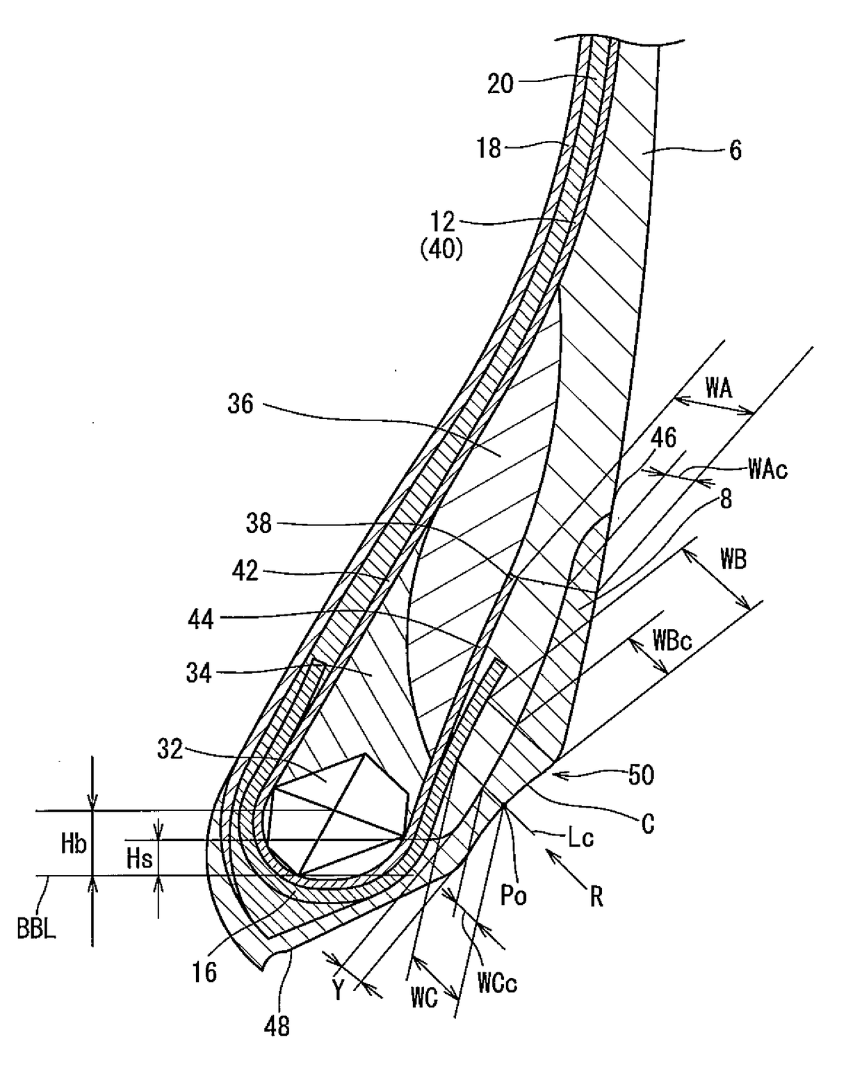
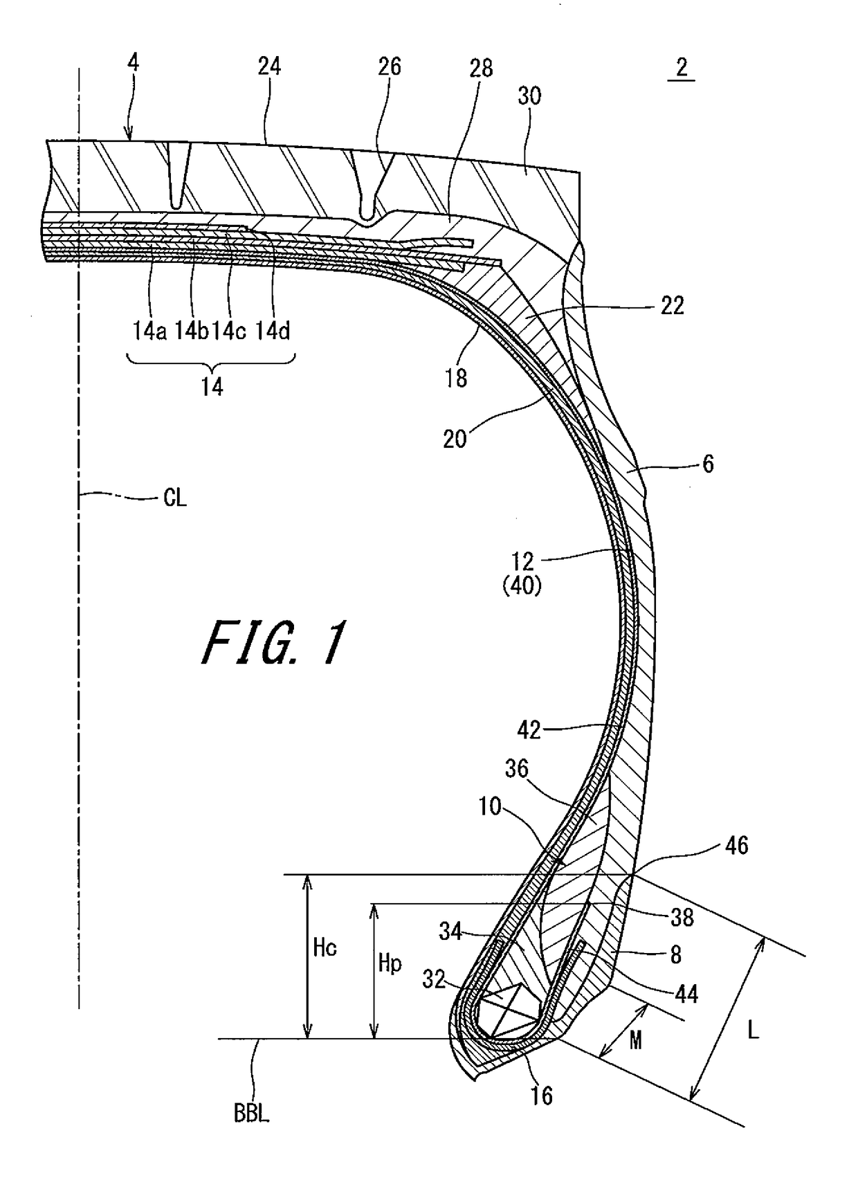
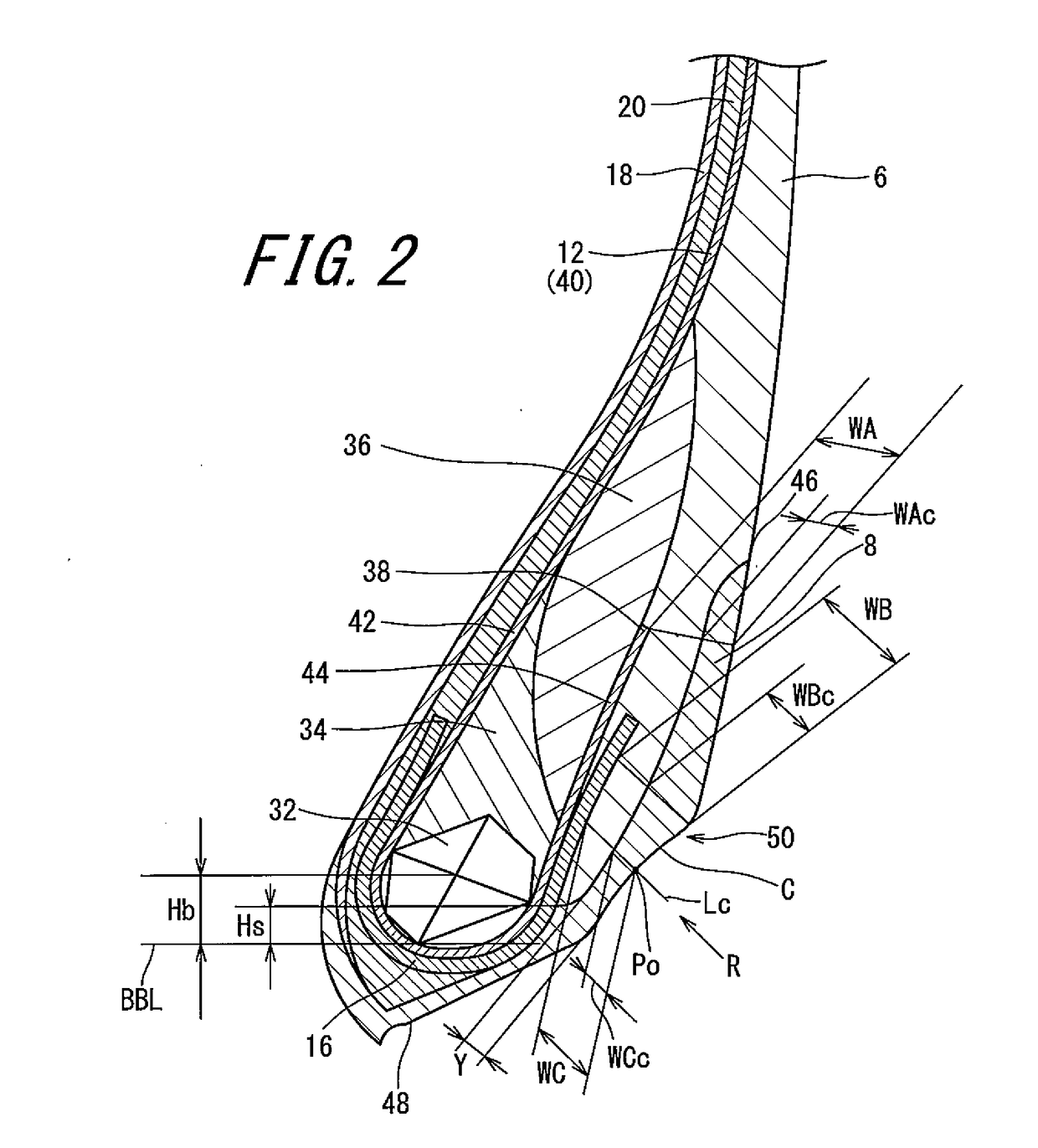
[0082]A tire of example 1 having the structure shown in FIG. 1 was obtained. The size of the tire was 11R22.5. The specifications of the tire were indicated in Table 1. In the tire, the sidewall extended to a position inward of the normal line Lc in the radial direction. This is indicated in the table as “inward of Lc” in the cell for “SW inner end position”. In the tire, the ratio (Hc / Hp) was 1.2, which is not indicated in the table. The ratio (Hs / Hb) was 0.6. The loss tangent LTs was 0.06 and the loss tangent LTc was 0.15. The complex elastic modulus Es was 5 MPa, and the complex elastic modulus Ec was 10 MPa.

example 2

[0086]A tire of example 2 was obtained in the same manner as in example 1 except that, in example 2, a sidewall did not extend to a position inward of the normal line Lc in the radial direction. “Outward of Lc” in the cell for “SW inner end position” in the table indicates that the sidewall did not extend to a position inward of the normal line Lc in the radial direction. In the tire, the ratio (Hs / Hb) was 3.0.

examples 3 to 6

[0087]Tires of examples 3 to 6 were each obtained in the same manner as in example 1 except that the curvature radius R had the value indicated in Table 2.


PUM


Abstract

In a tire 2, chafers 8 each extend from a position axially outward of a corresponding one of beads 10 to a position radially inward of the corresponding one of the beads 10. Sidewalls 6 extend to positions between the beads 10 and the chafers 8, respectively. The chafers 8 extend to positions outward of ends 38 of turned-up portions 44 of a carcass ply 40 in the radial direction. When a side surface 50 represents a portion, of an outer surface of each chafer 8, which contacts with a flange of a rim, an outline of the side surface 50 has an arc C that extends from a heel of the bead 10 portion and projects inward.

Description

[0001]This application claims priority on Patent Application No. 2016-218512 filed in JAPAN on Nov. 9, 2016. The entire contents of this Japanese Patent Application are hereby incorporated by reference.BACKGROUND OF THE INVENTIONField of the Invention[0002]The present invention relates to pneumatic tires. More specifically, the present invention relates to heavy duty pneumatic tires that are to be mounted to vehicles such as trucks and buses.Description of the Related Art[0003]It is important to reduce rolling resistance of a tire in order to reduce fuel consumption by the tire. When a tire rolls, deformation and restoration are repeated in the tire. Energy loss due to the deformation and restoration is a major factor in generation of rolling resistance of the tire. When a low heat generating rubber (rubber having a low loss tangent) is used for a tire, energy loss can be reduced.[0004]A tire has a chafer disposed inward of a sidewall in the radial direction. The chafer comes into c...

Claims


Application Information

Patent Timeline
Patent Type & Authority Applications(United States)
IPC IPC(8): B60C15/06
CPCB60C15/06B60C2015/0614B60C2013/006B60C2013/007B60C15/0009B60C15/04B60C2200/04B60C13/00B60C15/0027B60C15/024B60C15/0607
Inventor TANADA, KENICHIRO
Owner SUMITOMO RUBBER IND LTD
Why Eureka
Try Eureka