

Wastegate for an engine system
a wastegate and engine technology, applied in the direction of combustion engines, machines/engines, internal combustion piston engines, etc., can solve the problems of reducing flow efficiency and energy losses, and affecting the efficiency of combustion engines,
- Summary
- Abstract
- Description
- Claims
- Application Information
AI Technical Summary
Benefits of technology
Problems solved by technology
Method used
Image

Examples
first embodiment
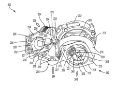
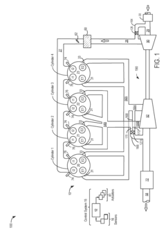
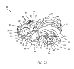
[0040]The following description relates to a turbocharger system with a bifurcated bypass passage configured with a wastegate to control exhaust flow around a twin scroll turbine and to an exhaust catalyst placed downstream of the turbine in an engine, as shown in FIG. 1. As depicted in FIG. 2A, an example engine turbocharger having a wastegate valve including a valve actuation mechanism to control exhaust flow within a bypass passage around the turbine and to the exhaust catalyst is disclosed. The wastegate valve may be adjusted to open or close by the actuator mechanism using various means including mechanical, hydraulic, electrical, and other suitable actuation methods. FIG. 2B shows a schematic view of the wastegate including a valve plate and a valve plate actuator. The wastegate also includes a passage with a curved interior surface that may act to direct exhaust flow delivered from engine cylinders (via the exhaust passage) to the exhaust catalyst.
second embodiment
[0041]FIG. 3A shows a first view of the wastegate valve in a closed wastegate position and having a passage having a constricted section formed on an internal wall of the passage. The wastegate valve may be adjusted into an open position to allow exhaust flow through an outlet of the wastegate, as shown in FIG. 3B. An alternative embodiment of the wastegate valve in an open position and having a passage with no constricted section formed on an internal wall of the passage is depicted in FIG. 3C. In this case, the exhaust gas may flow in multiple directions, as shown. The exhaust flow fanning out of the wastegate outlet, may impinge on walls of the exhaust passage downstream of the valve and cause turbulent flow conditions, which may lead to exhaust energy loss.
third embodiment
[0042]FIGS. 4A-4E show a wastegate valve that includes a rib extending from an inner portion of a valve plate. The rib may divide the valve plate into a first and a second section. The valve plate includes a rib that connects to a base plate, and extends outward into a wastegate passage. As an example, the rib may include a curved portion connected to a linear portion, as shown in FIG. 4D. A cross sectional view of the wastegate passage is depicted in FIG. 4E. In this case, the central wall bifurcates the passage into a first and a second side.
[0043]FIGS. 5A-5C show schematic views of a valve plate of a fourth embodiment of the wastegate valve. FIGS. 5A-5B show a first and second view, respectively of the valve plate of the fourth embodiment of the wastegate valve. FIG. 5C shows a third view of the valve plate of the fourth embodiment of the wastegate valve. FIGS. 6A-6B show schematic views of the fourth embodiment of the wastegate valve in a closed position. FIG. 6A shows a first v...
PUM
 Abstract
Description
Claims
Application Information